
R3102-R3103-HP 6600/HSR6600 Routers Layer 2 - WAN Configuration Guide

108
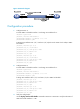
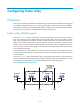
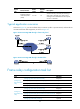
Figure 33 Network diagram
Configuration procedure
1. Configure Router A:
# Create HDLC link bundle interface 1 and assign an IP address for it.
<RouterA> system-view
[RouterA] interface hdlc-bundle 1
[RouterA-Hdlc-bundle1] ip address 1.1.1.1 24
[RouterA-Hdlc-bundle1] quit
# Assign POS interfaces POS 1/0/1 and POS 1/0/2 (both use the master clock mode) to HDLC
link bundle 1.
[RouterA] interface pos 1/0/1
[RouterA-Pos1/0/1] clock master
[RouterA-Pos1/0/1] link-protocol hdlc
[RouterA-Pos1/0/1] bundle id 1
[RouterA-Pos1/0/1] quit
[RouterA] interface pos 1/0/2
[RouterA-Pos1/0/2] clock master
[RouterA-Pos1/0/2] link-protocol hdlc
[RouterA-Pos1/0/2] bundle id 1
[RouterA-Pos1/0/2] quit
2. Configure Router B:
# Create HDLC link bundle interface 1 and assign an IP address for it.
<RouterB> system-view
[RouterB] interface hdlc-bundle 1
[RouterB-Hdlc-bundle1] ip address 1.1.1.2 24
[RouterB-Hdlc-bundle1] quit
# Assign POS interfaces POS 1/0/1 and POS 1/0/2 to HDLC link bundle 1.
[RouterB] interface pos 1/0/1
[RouterB-Pos1/0/1] link-protocol hdlc
[RouterB-Pos1/0/1] bundle id 1
[RouterB-Pos1/0/1] quit
[RouterB] interface pos 1/0/2
[RouterB-Pos1/0/2] link-protocol hdlc
[RouterB-Pos1/0/2] bundle id 1
[RouterB-Pos1/0/2] quit
3. Verify the configuration:
Use the display interface hdlc-bundle command on Router A or Router B to verify that the state of
HDLC link bundle interface 1 is UP.