
R3102-R3103-HP 6600/HSR6600 Routers MPLS Configuration Guide

176
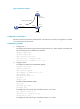
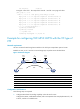
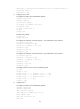
Figure 46 Network diagram
Device Interface IP address Device Interface IP address
CE 1 POS5/1/0 100.1.1.1/24
CE 2
POS5/1/0 100.1.1.2/24
PE 1 Loop0 10.0.0.1/32
P
Loop0
10.0.0.2/32
POS5/1/1 10.1.1.1/24 POS5/1/0 10.2.2.2/24
PE 2 Loop0 10.0.0.3/32
POS5/1/1 10.1.1.2/24
POS5/1/0 10.2.2.1/24
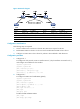
Configuration considerations
The following steps are required:
1. Create a remote CCC connection on the PEs. No static LSP is required on the PEs.
2. Enable MPLS L2VPN on the PEs. You do not need to enable MPLS L2VPN on the P device.
3. Configure two static LSPs on the P device for packets to be transferred in both directions.
Configuration procedure
1. Configure CE 1:
# Configure the link protocol as PPP on interface POS 5/1/0 (the interface connected to PE 1),
and configure an IP address for the interface.
<Sysname> system-view
[Sysname] sysname CE1
[CE1] interface pos 5/1/0
[CE1-POS5/1/0] link-protocol ppp
[CE1-POS5/1/0] ip address 100.1.1.1 24
2. Configure PE 1:
# Configure the LSR ID and enable MPLS globally.
<Sysname> system-view
[Sysname] sysname PE1
[PE1] interface loopback 0
[PE1-LoopBack0] ip address 10.0.0.1 32
[PE1-LoopBack0] quit
[PE1] mpls lsr-id 10.0.0.1
[PE1] mpls
[PE1-mpls] quit
# Enable L2VPN and MPLS L2VPN.
[PE1] l2vpn
[PE1-l2vpn] mpls l2vpn