
R3102-R3103-HP 6600/HSR6600 Routers MPLS Configuration Guide

179
Out-interface : POS5/1/1
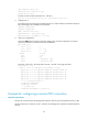
# Ping CE 2 from CE 1. The output shows that CE 1 and CE 2 can ping each other.
[CE1] ping 100.1.1.2
PING 100.1.1.2: 56 data bytes, press CTRL_C to break
Reply from 100.1.1.2: bytes=56 Sequence=1 ttl=255 time=180 ms
Reply from 100.1.1.2: bytes=56 Sequence=2 ttl=255 time=60 ms
Reply from 100.1.1.2: bytes=56 Sequence=3 ttl=255 time=10 ms
Reply from 100.1.1.2: bytes=56 Sequence=4 ttl=255 time=70 ms
Reply from 100.1.1.2: bytes=56 Sequence=5 ttl=255 time=60 ms
--- 100.1.1.2 ping statistics ---
5 packet(s) transmitted
5 packet(s) received
0.00% packet loss
round-trip min/avg/max = 10/76/180 ms
Example for configuring SVC MPLS L2VPN with the VC type of
PPP
Network requirements
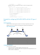
CEs are connected to PEs through POS interfaces. The link layer encapsulation protocol is PPP.
Establish an SVC, so CE 1 and CE 2 can exchange Layer 2 packets across the backbone.
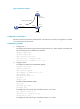
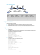
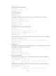
Figure 47 Network diagram
Device Interface IP address
Device
Interface
IP address
CE 1 POS5/1/0 100.1.1.1/24
CE 2
POS5/1/0 100.1.1.2/24
PE 1 Loop0 192.2.2.2/32 P Loop0 192.4.4.4/32
POS5/1/1 10.1.1.1/24
POS5/1/0 10.2.2.2/24
PE 2 Loop0 192.3.3.3/32
POS5/1/1 10.1.1.2/24
POS5/1/0 10.2.2.1/24
Configuration considerations
The following steps are required:
1. Configure MPLS basic forwarding capability on the PEs and P router:
Configure the LSR ID, enable MPLS and LDP, and run IGP (OSPF in this example) between PE 1, the
P device, and PE 2 to establish LSPs.
CE 1
CE 2
SVC
PE 1 PE 2P
POS5/1/1
POS5/1/1
POS5/1/0
POS5/1/0
POS5/1/0
POS5/1/1
POS5/1/0
POS5/1/0
Loop0 Loop0 Loop0