
R3102-R3103-HP 6600/HSR6600 Routers MPLS Configuration Guide

186
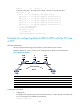
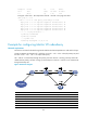
# Enable LDP globally.
[PE2] mpls ldp
[PE2-mpls-ldp] quit
# Configure the peer relationship with PE 1 so that the LDP remote session can be established
between them.
[PE2] mpls ldp remote-peer 2
[PE2-mpls-ldp-remote-2] remote-ip 192.2.2.2
[PE2-mpls-ldp-remote-2] quit
# Configure the interface connected to the P device, and enable LDP on the interface.
[PE2] interface serial 2/1/1
[PE2-Serial2/1/1] link-protocol ppp
[PE2-Serial2/1/1] ip address 10.2.2.1 24
[PE2-Serial2/1/1] mpls
[PE2-Serial2/1/1] mpls ldp
[PE2-Serial2/1/1] quit
# Configure OSPF on PE 2 for establishing LSPs.
[PE2] ospf
[PE2-ospf-1] area 0
[PE2-ospf-1-area-0.0.0.0] network 192.3.3.3 0.0.0.0
[PE2-ospf-1-area-0.0.0.0] network 10.2.2.0 0.0.0.255
[PE2-ospf-1-area-0.0.0.0] quit
[PE2-ospf-1] quit
# Create a Martini VC on the interface connected to CE 2. The interface requires no IP address.
[PE2] interface serial 2/1/0
[PE2-Serial2/1/0] mpls l2vc 192.2.2.2 101
[PE2-Serial2/1/0] quit
5. Configure CE 2:
# Configure the link protocol type as PPP on interface Serial 2/1/0 (the interface connected to the
PE 2), and configure an IP address for the interface.
<Sysname> system-view
[Sysname] sysname CE2
[CE2] interface serial 2/1/0
[CE2-Serial2/1/0] link-protocol ppp
[CE2-Serial2/1/0] ip address 100.1.1.2 24
6. Verify your configuration:
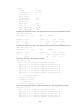
# Display VC information on PE 1. The output shows that a VC has been established.
[PE1] display mpls l2vc
Total ldp vc : 1 1 up 0 down 0 blocked
Transport Client VC Local Remote
VC ID Intf State VC Label VC Label
101 S2/1/0 up 1024 1025
# Display VC information on PE 2. The output shows that a VC has been established.
[PE2] display mpls l2vc
Total ldp vc : 1 1 up 0 down 0 blocked