
R3102-R3103-HP 6600/HSR6600 Routers MPLS Configuration Guide
33
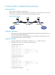
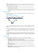
[RouterC] static-lsp ingress CtoA destination 11.1.1.0 24 nexthop 20.1.1.1 out-label
40
# Configure the LSP transit node, Router B.
[RouterB] static-lsp transit CtoA incoming-interface serial 2/1/1 in-label 40 nexthop
10.1.1.1 out-label 70
# Configure the LSP egress node, Router A.
[RouterA] static-lsp egress CtoA incoming-interface serial 2/1/0 in-label 70
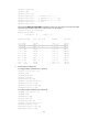
6. Verify the configuration:
# Execute the display mpls static-lsp command on each router to view static LSP information. Take
Router A as an example:
[RouterA] display mpls static-lsp
total statics-lsp : 2
Name FEC I/O Label I/O If State
AtoC 21.1.1.0/24 NULL/30 -/S2/1/0 Up
CtoA -/- 70/NULL S2/1/0/- Up
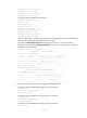
# On Router A, test the connectivity of the LSP from Router A to Router C.
[RouterA] ping lsp -a 11.1.1.1 ipv4 21.1.1.0 24
LSP Ping FEC: IPV4 PREFIX 21.1.1.0/24 : 100 data bytes, press CTRL_C to break
Reply from 20.1.1.2: bytes=100 Sequence=1 time = 2 ms
Reply from 20.1.1.2: bytes=100 Sequence=2 time = 2 ms
Reply from 20.1.1.2: bytes=100 Sequence=3 time = 1 ms
Reply from 20.1.1.2: bytes=100 Sequence=4 time = 2 ms
Reply from 20.1.1.2: bytes=100 Sequence=5 time = 2 ms
--- FEC: IPV4 PREFIX 21.1.1.0/24 ping statistics ---
5 packet(s) transmitted
5 packet(s) received
0.00% packet loss
round-trip min/avg/max = 1/1/2 ms
# On Router C, test the connectivity of the LSP from Router C to Router A.
[RouterC] ping lsp -a 21.1.1.1 ipv4 11.1.1.0 24
LSP Ping FEC: IPV4 PREFIX 11.1.1.0/24 : 100 data bytes, press CTRL_C to break
Reply from 10.1.1.1: bytes=100 Sequence=1 time = 3 ms
Reply from 10.1.1.1: bytes=100 Sequence=2 time = 2 ms
Reply from 10.1.1.1: bytes=100 Sequence=3 time = 2 ms
Reply from 10.1.1.1: bytes=100 Sequence=4 time = 2 ms
Reply from 10.1.1.1: bytes=100 Sequence=5 time = 2 ms
--- FEC: IPV4 PREFIX 11.1.1.0/24 ping statistics ---
5 packet(s) transmitted
5 packet(s) received
0.00% packet loss
round-trip min/avg/max = 2/2/3 ms