
R3303-HP 6600/HSR6600 Routers MPLS Configuration Guide

120
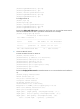
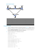
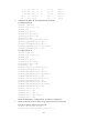
Create a bypass LSP that traverses the path Router B Router E Router C. Router B is the PLR and Router →→
C is the MP.
Explicitly route the primary TE tunnel and the bypass TE tunnel with the signaling protocol being RSVP-TE.
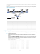
Figure 31 Network diagram
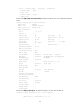
Device Interface IP address
Device
Interface
IP address
Router A Loop0 1.1.1.1/32 Router E Loop0 5.5.5.5/32
GE 2/1/1 2.1.1.1/24
POS 5/1/0 3.2.1.2/24
Router B Loop0 2.2.2.2/32
POS 5/1
3.3.1.1/24
GE 2/1/1 2.1.1.2/24 Router C Loop0 3.3.3.3/32
GE 2/1/2 3.1.1.1/24
GE 2/1/1 4.1.1.1/24
POS 5/1/0 3.2.1.1/24
GE 2/1/2 3.1.1.2/24
Router D Loop0 4.4.4.4/32 POS 5/1/0 3.3.1.2/24
GE 2/1/1 4.1.1.2/24
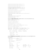
Configuration procedure
1. Configure IP addresses and masks for the interfaces according to Figure 31. (Details not shown.)
2. Configure the IGP protocol:
# Enable IS-IS to advertise host routes with LSR IDs as destinations on each node. (Details not
shown.)
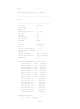
# Execute the display ip routing-table command on each router. You can see that all nodes have
learned the host routes of other nodes with LSR IDs as destinations. Take Router A for example:
<RouterA> display ip routing-table
Routing Tables: Public
Destinations : 13 Routes : 13
Destination/Mask Proto Pre Cost NextHop Interface
1.1.1.1/32 Direct 0 0 127.0.0.1 InLoop0
2.1.1.0/24 Direct 0 0 2.1.1.1 GE2/1/1
2.1.1.1/32 Direct 0 0 127.0.0.1 InLoop0
2.2.2.2/32 ISIS 15 10 2.1.1.2 GE2/1/1
3.1.1.0/24 ISIS 15 20 2.1.1.2 GE2/1/1
3.2.1.0/24 ISIS 15 20 2.1.1.2 GE2/1/1
3.3.1.0/24 ISIS 15 30 2.1.1.2 GE2/1/1
3.3.3.3/32 ISIS 15 20 2.1.1.2 GE2/1/1