
R3303-HP 6600/HSR6600 Routers MPLS Configuration Guide


191
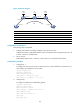
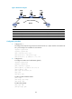
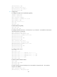
Create two Martini VCs between CE 1 and CE 2, one is CE 1 – PE 1 – PE 2 – CE 2 (the primary VC) and
the other is CE 1 – PE 1 – PE 3 – CE 2 (the backup VC).
CE 1 and CE 2 communicate through the primary VC when this VC is working correctly. When PE 1
detects that the primary VC fails, it brings up the backup VC so that CE 1 and CE 2 can communicate
through the backup VC.
Figure 49 Network diagram
Device Interface IP address
Device
Interface
IP address
CE 1 S2/1/0 100.1.1.1/24 PE 2 Loop0 2.2.2.2/32
S2
/
1
/
0 100.2.1.1/24 sub
S2
/
1
/
0
12.1.1.2/24
S2
/
1
/
1 100.3.1.1/24
PE 3
Loop0
3.3.3.3/32
PE 1 Loop0 1.1.1.1/32 S2/1/0 13.1.1.3/24
S2
/
1
/
1 12.1.1.1/24
CE 2
S2
/
1
/
0
100.1.1.2/24
S2
/
1
/
2 13.1.1.1/24
S2
/
1
/
1
100.2.1.2/24
Configuration procedure
1. Configure CE 1:
# Assign IP address to interfaces.
<Sysname> system-view
[Sysname] sysname CE1
[CE1] interface serial 2/1/0
[CE1-Serial2/1/0] link-protocol ppp
[CE1-Serial2/1/0] ip address 100.1.1.1 24
[CE1-Serial2/1/0] ip address 100.2.1.1 24 sub
[CE1-Serial2/1/0] quit
[CE1] interface serial 2/1/1
[CE1-Serial2/1/1] link-protocol ppp
[CE1-Serial2/1/1] ip address 100.3.1.1 24
[CE1-Serial2/1/1] quit
# Configure IS-IS.
[CE1] isis 1
[CE1-isis-1] network-entity 10.0000.0000.0001.00
[CE1-isis-1] quit
[CE1] interface serial 2/1/0
[CE1-Serial2/1/0] isis enable 1