HP 6600/HSR6600/HSR6800 Router Series Interface Module Guide Part number: 5998-1524 Document version: 6PW103-20140126
Legal and notice information © Copyright 2014 Hewlett-Packard Development Company, L.P. No part of this documentation may be reproduced or transmitted in any form or by any means without prior written consent of Hewlett-Packard Development Company, L.P. The information contained herein is subject to change without notice.
Contents Interface module list ····················································································································································· 3 LPU list ··········································································································································································· 5 MPU list ·········································································································································
Documents ······························································································································································ 58 Websites································································································································································· 58 Conventions ···························································································································································
Interface module list The full names and abbreviations of the interface modules are listed below. To simplify the descriptions in the guide, abbreviations are used to identify the interface modules.
J# Full name Abbreviation Hight JG366A RT-SAP-4EXP SAP-4EXP 1.
LPU list The full names and abbreviations of the LPUs are listed below. To simplify the descriptions in the guide, abbreviations are used to identify the LPUs. Table 2 LPU list J# Full name Abbreviation Hight JG357A RT-FIP-10 FIP-10 1.8 inch JC166B RT-FIP-110-H3 FIP-110 1.8 inch JG358A RT-FIP-20 FIP-20 1.8 inch JC167B RT-FIP-210-H3 FIP-210 1.8 inch JG671A RT-FIP-300 FIP-300 1.8 inch JG672A RT-FIP-310 FIP-310 1.8 inch JG360A RT-FIP-600 FIP-600 1.
MPU list The full names and abbreviations of the MPUs are listed below. To simplify the descriptions in the guide, abbreviations are used to identify the MPUs. Table 3 MPU list J# Full name Abbreviation Hight JC165A RT-RPE-X1-H3 RPE-X1 1.8 inch JC566A RT-RSE-X1-H3 RSE-X1 1.8 inch JG364A RT-RSE-X2 RSE-X2 1.8 inch JG355A RT-MCP-X1 MCP-X1 1.8 inch JG356A RT-MCP-X2 MCP-X2 1.8 inch JG778A RT-MCP-X2-TAA MCP-X2-TAA 1.8 inch JG779A RT-RSE-X2-TAA RSE-X2-TAA 1.
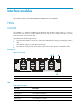
Interface modules The interface modules of the 6600/HSR6600/HSR6800 are hot swappable. HIMs HIM-8FE The HIM-8FE is a 10Base-T/100Base-TX Fast Ethernet (FE) interface module used by a router to communicate with a LAN. It provides eight RJ-45 ports, each of which supports the Layer 3 routing function and has a bi-color status LED. The HIM-8FE has the following features: • The transmission distance can be up to 100 meters (328.08 ft) if a category-5 twisted pair cable is used.
LED status Description Flashing green Data is being received or transmitted at 100 Mbps. Interface specifications Table 5 Interface specifications Item Specification Connector type RJ-45 Number of interfaces 8 Interface standards 802.3, 802.3u Interface type Auto MDI/MDI-X Cable type Straight-through/crossover cable Transmission distance 100 m (328.
Front panels Figure 2 Front panel of HIM-8GBE (1) GE port (2) GE port status LED (3) Captive screw (4) Ejector lever Figure 3 Front panel of HIM-4GBE 2 3 1 4 (1) Captive screw (2) GE port (3) GE port status LED (4) Ejector lever LEDs Table 6 LED description LED status Description Off No link is present or the cable is faulty. Steady green A 1000 Mbps link is present. Flashing green Data is being received or transmitted at 1000 Mbps. Steady yellow A 10/100 Mbps link is present.
Interface specifications Table 7 Interface specifications Item Specification Connector type RJ-45 Number of interfaces • HIM-4GBE: 4 • HIM-8GBE: 8 Interface standards 802.3, 802.3u, 802.3ab Interface type Auto MDI/MDI-X Cable type Straight-through/crossover Ethernet cable Transmission distance 100 m (328.
Front panels Figure 4 Front panel of HIM-4GBP (1) Captive screw (2) SFP port (3) SFP port status LED (4) Ejector lever Figure 5 Front panel of HIM-8GBP (1) Captive screw (2) SFP port (3) SFP port status LED (4) Ejector lever LEDs Table 8 LED description LED status Description Off No link is present. Steady green A 1000 Mbps link is present. Flashing green The interface is receiving or sending data at 1000 Mbps. Steady yellow A 100 Mbps link is present.
Interface specifications Table 9 Interface specifications Item Specification Connector type SFP Number of interfaces • HIM-4GBP: 4 • HIM-8GBP: 8 Interface standards 802.3, 802.3u, 802.3ab Supported frame format • Ethernet_II • Ethernet_SNAP Type Short haul Medium haul Long haul Long haul Ultra-long haul Min. –9.5 dBm –9 dBm –2 dBm –4 dBm –4 dBm Max.
HIM-1EXP The HIM-1EXP is a 1-port 10 GE transceiver module. It provides one 10-Gigabit Small Form-Factor Pluggable (XFP) port and supports switchover between LAN/WAN PHY modes. A LED is provided on the front panel to show the operation state. Front panel Figure 6 Front panel (1) Captive screw (2) Ejector lever (3) XFP port (4) XFP port carrier signal LED (LINK/ACT) LED Table 10 LED description LED status Description Off No link is present.
Item Specification Receiving sensitivity –7.5 dBm –10.3 dBm –11.3 dBm Central wavelength 850 nm 1310 nm 1550 nm Max. transmission distance 0.3 km (0.19 miles) 10 km (6.21 miles) 40 km (24.86 miles) Fiber type 62.5/125 μm multi-mode 9/125 μm single-mode 9/125 μm single-mode NOTE: In LAN PHY mode, 10GBase-R is supported. In WAN PHY mode, 10GBase-W is supported. Interface cable The HIM-1EXP must work with an XFP transceiver module and an optical fiber with LC-type connectors.
Front panels Figure 7 Front panel of HIM-CL1P (1) SFP port carrier signal LED (LINK/ACT) (2) SFP port loopback/alarm LED (LP/AL) of SFP port (3) SFP port (4) Captive screw (5) Ejector lever Figure 8 Front panel of HIM-CL2P (1) SFP port carrier signal LED (LINK/ACT) (2) SFP port loopback/alarm LED (LP/AL) (3) SFP port (4) Captive screw (5) Ejector lever LEDs Table 12 LED description LED LINK/ACT (Green) LP/AL (Yellow) Status Description Off No link is present. On A 155.
Interface specifications Table 13 Interface specifications Item Specification Connector type SFP/LC Number of interfaces • HIM-CL1P: 1 • HIM-CL2P: 2 Interface standards SONET OC-3/SDH STM-1 Interface speed 155.52 Mbps Type Short haul Medium haul Long haul Ultra-long haul Min. –19.0 dBm –15.0 dBm –5.0 dBm –5.0 dBm Max. –14.0 dBm –8.0 dBm 0 dBm 0 dBm Receiving sensitivity –30.0 dBm –28.0 dBm –34.0 dBm –34.0 dBm Overload optical power –14.0 dBm –7.0 dBm –9.0 dBm –10.
• The configuration of the operating mode can take effect only after you hot-plug the interface module or reboot the device. It is recommended to remove and insert the module to bring the configuration into effect. • The configuration of the operating mode takes effect for all the interfaces on the interface modules. NOTE: The HIM-CLS1P/HIM-CLS2P does not support channelizing OC-3/STM-1 into DS1s or E1s.
LEDs Table 14 LED description LED LINK/ACT (Green) LP/AL (Yellow) Status Description Off No link is present. On A 155.52 Mbps link is present. Flashing The SFP port is receiving or sending data at 155.52 Mbps. Off No loopback or alarm exists. On The interface is in loopback state. Flashing There is at least one alarm.
• The interface module can be configured with the card-mode command to operate in OC-3/STM-1 POS or OC-12/STM-4 POS mode. • The configuration of the operating mode can take effect only after you hot-plug the interface module or reboot the device. It is recommended to remove and insert the module to bring the configuration into effect. • The configuration of the operating mode takes effect for all the interfaces on the interface module.
Figure 12 Front panel 1 8 7 6 5 3 4 2 (1) Captive screw (2) Ejector lever (3) SFP port carrier signal LED (LINK/ACT) (4) SFP port loopback/alarm LED (LP/AL) (5) SFP port 3 (155 Mbps) or SFP port 1 (622 Mbps) (6) SFP port 2 (155 Mbps) or SFP port 0 (622 Mbps) (7) SFP port 1 (155 Mbps) (8) SFP port 0 (155 Mbps) LEDs Table 16 LED description LED LINK/ACT (Green) LP/AL (Yellow) Status Description Off No link is present. On A 155.52/622.08 Mbps link is present.
Item Specification Receiving sensitivity –30.0 dBm –28.0 dBm –34.0 dBm –34.0 dBm Overload optical power –14.0 dBm –7.0 dBm –9.0 dBm –10.0 dBm Central wavelength 1310 nm 1310 nm 1310 nm 1550 nm Max. transmission distance 2 km (1.24 miles) 15 km (9.32 miles) 40 km (24.86 miles) 80 km (49.71 miles) Fiber type 62.5/125 μm multi-mode 9/125 μm single-mode 9/125 μm single-mode 9/125 μm single-mode OC-12 interface (622.08 Mbps) Type Medium haul Long haul Ultra-long haul Min. –15.
Front panel Figure 13 Front panel of HIM-PS1P (1) Captive screw (2) Ejector lever (3) SFP port carrier signal LED (LINK/ACT) (4) SFP port loopback/alarm LED (LP/AL) (5) SFP port (2.5 Gbps) LEDs Table 18 LED description LED LINK/ACT (Green) LP/AL (Yellow) Status Description Off No link is present. On A 2488.32 Mbps link is present. Flashing The SFP port is receiving or sending data at 2488.32 Mbps. Off No loopback or alarm exists. On The interface is in loopback state.
Item Specification Overload optical power –3.0 dBm 0.0 dBm –9.0 dBm –8.0 dBm Central wavelength 1310 nm 1310 nm 1310 nm 1550 nm Max. transmission distance 2 km (1.24 miles) 15 km (9.32 miles) 40 km (24.86 miles) 80 km (49.71 miles) Fiber type 9/125 μm single-mode 9/125 μm single-mode 9/125 μm single-mode 9/125 μm single-mode Interface cable The HIM-PS1P must work with an SFP transceiver module and an optical fiber with LC-type connectors.
Figure 15 Front panel of HIM-AL2P (1) Captive screw (2) Ejector lever (3) SFP port (4) SFP port carrier signal LED (LINK/ACT) (5) SFP port loopback/alarm LED (LP/AL) LEDs Table 20 LED description LED LINK/ACT (Green) LP/AL (Yellow) Status Description Off No link is present. On A 155.52 Mbps link is present. Flashing The SFP port is receiving or sending data at 155.52 Mbps. Off No loopback or alarm exists. On The port is in loopback state. Flashing There is at least one alarm.
Item Specification Central wavelength 1310 nm 1310 nm 1310 nm 1550 nm Max. transmission distance 2 km (1.24 miles) 15 km (9.32 miles) 40 km (24.86 miles) 80 km (49.71 miles) Fiber type 62.5/125 μm multi-mode 9/125 μm single-mode 9/125 μm single-mode 9/125 μm single-mode Interface cable The HIM-AL1P/HIM-AL2P must work with an SFP transceiver module and an optical fiber with LC-type connectors.
LEDs Table 22 LED description LED RPR status Status Description PASSTHRU Off The node is not in PASSTHRU. (Green) On The node is in PASSTHRU. MATESYNC Off The mate interface is not synchronized. (Green) On The mate interface is synchronized. Off No WRAP exists. On WRAP occurs on this node. Flashing (0.5 Hz) WRAP occurs on another node. Off No STEER exists. On STEER occurs on this node. Flashing (0.5 Hz) STEER occurs on another node. Off No carrier signals are being received.
Item Specification Fiber type 9/125 μm single-mode 9/125 μm single-mode 9/125 μm single-mode 9/125 μm single-mode Interface cable Test optical power before choosing a transceiver module and optical fiber, because an optical fiber connector might have transmitted for dozens of kilometers from a user fiber. The HIM-RS2P supports the connection of Mate interfaces within the module. All Mate interfaces in a module can be connected without external transceiver modules or fibers.
LED SFP POS-155M/PO S-622M Status Description Steady green A 155.52/622 Mbps link is present. LINK/ACT/LP/ AL Flashing green Data is being transmitted or received. Steady yellow A loopback exists. (Yellow/Green) Flashing yellow An alarm has occurred. Off No link is present. Interface specifications Table 25 Ethernet fiber port specifications Item Specification Connector type SFP Number of interfaces 0 to 8 Interface standards 802.3, 802.3u, 802.
Item Specification Receiving sensitivity –30.0 dBm –28.0 dBm –34.0 dBm –34.0 dBm Overload optical power –14.0 dBm –7.0 dBm –9.0 dBm –10.0 dBm Central wavelength 1310 nm 1310 nm 1310 nm 1550 nm Max. transmission distance 2 km (1.24 miles) 15 km (9.32 miles) 40 km (24.86 miles) 80 km (49.71 miles) Fiber type 62.5/125 μm multi-mode 9/125 μm single-mode 9/125 μm single-mode 9/125 μm single-mode OC-12 interface (622.08 Mbps) Type Medium haul Long haul Ultra-long haul Min. –15.
Front panels Figure 18 Front panel of MIM-8E1(75) (1) DB-68 connector (2) Carrier signal LED (LINK/ACT) (3) Captive screw (4) Loopback/alarm LED (LP/AL) Figure 19 Front panel of MIM-8E1(75)-F The front panel of MIM-8E1(75)-F is similar to that of MIM-8E1(75). LEDs Table 27 LED description LED LINK/ACT (Green) LP/AL (Yellow) Status Description Off No carrier signals are being received. On Carrier signals are being received. Flashing Data is being transmitted or received.
Item Specification Working modes E1, CE1, and FE1 (supported by the MIM-8E1(75)-F only) Services supported • Backup • Terminal access service Interface cable The MIM-8E1(75) or MIM-8E1(75)-F provides eight E1 ports and uses a 75-ohm splitter cable. At one end of this 16-core coaxial cable is a DB-68 connector used to connect to the device, and at the other end are 16 BNC connectors used to connect to the peer devices. NOTE: • The MIM-8E1(75)/MIM-8E1(75)-F does not support ISDN PRI.
Figure 21 Front panel of MIM-8T1-F The front panel of the MIM-8T1-F is similar to that of the MIM-8T1. Inteface specifications Table 29 Interface specifications Item Specification Connector type RJ-45 Number of interfaces 1 Interface standard • • • • • G.703/T1 102 G.704 AT&T TR 54016 AT&T TR 62411 ANSI T1.403 Interface speed 1.
NOTE: • The MIM-8T1/MIM-8T1-F does not support ISDN PRI. • For the MIM-8T1, if you use the timeslot binding command on the controller T1 interface, the system automatically creates the corresponding serial interface, on which you can make configurations. The MIM-8T1-F does not have a controller T1 interface, and a physical interface corresponds to one and only one serial interface, which is automatically created without the need of additional configuration.
LED Status Description Off No loopback or alarms occur. On The interface is in loopback state. At least one alarm of the type of AIS, LFA, or RAI has occurred. LP/AL Flashing • LFA—Loss of frame alignment. • AIS—Alarm indication signal. • RAI—Remote alarm indication. Interface specifications Table 32 Interface specifications Item Specification Connector type SMB Number of interfaces 2 Interface standards G. 703, G.704, G.751 Interface speed 34.
NOTE: • T3 represents the tertiary group rate of the T series in the TDM system, which is 44.736 Mbps. • A T3 channel can be channelized into 28 T1 channels through the demultiplex processes of T23 and T12, with each T1 channel supporting both the T1 and CT1 operating modes. T23 indicates either T2-to-T3 multiplex or T3-to-T2 demultiplex, and T12 indicates T1-to-T2 multiplex or T2-to-T1 demultiplex. T23 and T12 discussed here represent the demultiplex process.
Item Specification Interface standards • • • • • • G.703 G.704 G.752 AT&T TR 54014 AT&T TR 62415 ANSI T1.107 Interface speed 44.736 Mbps Cable type 75-ohm T3 coaxial cable Working modes T3/CT3 Services supported T3 leased line Interface cable The MIM-1CE3 provides two SMB interfaces, with one interface acting as the transmission end (Tx) and the other as the receiving end (Rx).
Front panel Figure 24 Front panel (1) Captive screw (2) Carrier signal LED (LINK/ACT) (3) Loopback/alarm LED (LP/AL) (4) SFP port (155 Mbps) LEDs Table 35 LED description LED LINK/ACT Status Description Off No carrier signals are being received. On Carrier signals are being received. Flashing Data is being transmitted or received. Off No loopback or alarms occur. On The interface is in loopback state. At least one alarm of the type of AIS, LFA, or RAI has occurred.
Item Specification Interface speed and duplex mode • 1000 Mbps • Full duplex Interface cable Select fibers according to the optical modules to be installed. For the appearance and connection of interface cables, see "Connecting an optical interface cable" WARNING! Do not look directly at any working optical interface modules because invisible rays emitted from the SFP port might hurt your eyes.
Figure 27 Front panel of MIM-8SAE (1) Serial interface (7) (2) Serial interface 7 LINK/ACT LED (3) Captive screw (4) Serial interface 3 LINK/ACT LED (5) Serial interface (3) LEDs • A LINK LED and an ACT LED are provided for each channel of the MIM-2SAE/MIM-4SAE. • The MIM-8SAE provides only one LED for each channel. Table 37 MIM-2SAE/MIM-4SAE LED description LED LINK ACT Status Description Off No link is present. On A link is present. Off No data is being received or transmitted.
Item Specification (in synchronous mode) Cable type • • • • • • • • • • Services supported V.24 (RS-232) DTE cable V.24 (RS-232) DCE cable V.35 DTE cable V.35 DCE cable X.21 DTE cable X.
SAP-48GBE The SAP-48GBE is a 10Base-T/100Base-TX/1000Base-T auto-sensing Ethernet service module developed by HP. The SAP-48GBE provides 48 RJ-45 interfaces, all of which feature Layer 3 routing and high-performance Layer 2 switching. Each interface uses a bi-color LED indicating the running status of the interface. In addition, the SAP-48GBE uses a run LED (RUN) to show the running status of the service module.
LED GE 0 to GE 47 (Yellow/green) Status Description Slow flashing (1 Hz) The SAP-48GBE is operating correctly. Fast flashing (8 Hz) Application program is being loaded (in this case, never power off the device or hot-swap the SAP-48GBE; otherwise, the SAP-48GBE might be damaged). Off No link is present or the cable is faulty. Steady green A 1000 Mbps link is present Flashing green Data is being received or transmitted at 1000 Mbps. Steady yellow A 10/100 Mbps link is present.
Front panels Figure 29 Front panel (1) SFP port (2) Captive screw (3) System status LED (RUN) (4) Ejector lever (5) SFP port status LED Specifications Table 43 Specifications Item Specification Processor Multi-core MIPS processor with ASIC chips Flash 4 MB Memory type and size • DDR2 SDRAM • 2 GB (default, two 1 GB memory modules) CAUTION: Use two DDR2 SDRAM modules of the same size at a time. NVRAM 128 KB Max.
Interface specifications Table 45 Interface specifications Item Specification Connector type SFP Number of interfaces 24 Interface standards 802.3, 802.3u, and 802.3ab Supported frame format • Ethernet_II • Ethernet_SNAP Type Short haul Medium haul Long haul Long haul Ultra-long haul Min. –9.5 dBm –9 dBm –2 dBm –4 dBm –4 dBm Max.
SAP-48GBP The SAP-48GBP is a 48-port 100/1000 Mbps auto-sensing optical Ethernet service module. It provides 48 SFP ports, all of which feature Layer 3 routing and high-performance Layer 2 switching. Each port uses a bi-color LED indicating the running status of the port. In addition, the SAP-48GBP uses a run LED (RUN) to show the running status of the module.
LED SFP 0 to SFP 47 (Yellow/green) Status Description Off No link is present or the cable is faulty. Steady green A 1000 Mbps link is present Flashing green Data is being received or transmitted at 1000 Mbps. Steady yellow A 100 Mbps link is present. Flashing yellow Data is being received or transmitted at 100 Mbps. Interface specifications Table 48 Interface specifications Item Specification Connector type SFP Number of interfaces 48 Interface standards 802.3, 802.3u, and 802.
Interface cable • When working with SFP transceiver modules, the SAP-48GBP must use an optical fiber with LC-type connectors. • When working with transceiver modules supporting fiber-to-copper conversion, the SAP-48GBP uses category-5 straight-through or crossover Ethernet cables when operating at 10/100 Mbps, and uses category-6 cable (recommended) when operating at 1000 Mbps.
LEDs Table 50 LED description LED Status Description Off No power input is available or the SAP-4EXP has failed. Slow flashing (1 Hz) The SAP-4EXP is operating correctly. Application program is being loaded or the SAP-4EXP is not operating. RUN (Green) Fast flashing (8 Hz) CAUTION: To avoid hardware damage, do not power off the router, or insert or remove the SAP-4EXP when the software image is being loaded. Off No link is present. SFP+ 0 to SFP+ 3 Steady green A 10 Gbps link is present.
Connecting the interface cables Connecting an Ethernet interface cable Appearance of an Ethernet cable Figure 32 Ethernet cable 10/100 Mbps Ethernet uses category-5 twisted pair cables, while 1000 Mbps Ethernet uses category-5 enhanced or category-6 twisted pair cables. Twisted pair cables include straight-through cables and crossover cables. Category-5 cables provide a transmission frequency of 100 MHz for voice and data transmission; they are mainly used in 100Base-T and 10Base-T networks.
Pinout No. A B 8 Brown Brown Pinout No. A B 1 Orange/white Green/white 2 Orange Green 3 Green/white Orange/white 4 Blue Blue 5 Blue/white Blue/white 6 Green Orange 7 Brown/white Brown/white 8 Brown Brown Table 53 Crossover cable pinouts NOTE: Strictly follow the pinouts in the above tables when identifying or making the two types of Ethernet cables; otherwise, the communication quality might be affected. Connecting an Ethernet cable 1.
SFP+ transceiver module SAP-4EXP XFP transceiver module HIM-1EXP SFP transceiver module Table 55 100-Mbps SFP transceiver module attributes Product code Model Central wavelengt h(nm) Conn ector Fiber Mode Optical fiber(μm) Transmissi on rate(Mbps) Max. transmission distance JD090A SFP-FE-LH40SM1310 1310 LC SMF 9/125 155 40 km (24.86 miles) JD091A SFP-FE-LH80SM1550 1550 LC SMF 9/125 155 80 km (49.71 miles) JD100A SFP-FE-LX-SM 1310-BIDI TX:1310 LC SMF 9/125 155 15 km (9.
Product code Model Central wavelen gth(nm) Connec tor Fiber Mode Optical fiber(μm) Transmissio n rate(Mbps) Max. transmission distance JF830A SFP-622M-LH40SM1310 1310 LC SMF 9/125 622 40 km (24.86 miles) JF831A SFP-622M-LH80SM1550 1550 LC SMF 9/125 622 80 km (49.71 miles) Table 57 1000-Mbps SFP transceiver module attributes Product code Model Central wavelengt h(nm) Connect or Fiber Mode Optical fiber(μm) Transmissio n rate(Mbps) Max.
SFP+ transceiver module Table 59 SFP+ transceiver module attributes Product code Model Central wavelength( nm) Conne ctor Fiber Mode JD092B SFP-XG-SX-M M850-A 850 LC MMF JD094B SFP-XG-LX-S M1310 1310 LC SMF JG234A SFP-XG-LH40 -SM1550 1550 LC Transmissi on rate(Gbps) Max. transmission distance 10.31 300 m (984.25 ft) 9/125 10.31 10 km (6.21 miles) SMF 9/125 10.31 40 km (24.86 miles) Optical fiber(μm) 50/125 62.
Connecting an E1 interface cable E1 cable appearance and applicable models Table 61 E1 cable appearance and applicable models Product number JD512A JD927A Cable Applicable models Appearance 8-port E1 75-ohm cable MIM-8E1 MIM-8E1-F 1 x D68 < ---- > 16 x BNC Connecting the cable When connecting the interface cable, pay attention to the mark on the interface to avoid wrong insertion, which might damage the interface module or even the host.
Figure 33 Connecting the 8E1 splitter cable (1) { If the 75-ohm 8E1 splitter cable need be extended, you can connect the BNC connector of the cable to the coaxial cable connector and connect the other end of the coaxial cable connector to the peer device through a 75-ohm E1 trunk cable. Figure 34 Connecting the 8E1 splitter cable (2) ... 3. Examine the LINK LED after connection. { { If the LED is on, the optical fiber link is present.
NOTE: • The Tx end of the cable must be connected to the Rx end of the peer device, and the Rx end of the cable to the Tx end of the peer device. • The coaxial cable connector and 75-ohm E1 trunk cable are optional accessories to be separately ordered if needed.
Connecting the cable 1. Connect the SMB connector of an E3/T3 cable to the Tx port on the interface module and another end to the Rx port on the device to be connected. 2. Connect the SMB connector of another E3/T3 cable to the Rx port of interface module and another end to the Tx port on the device to be connected. 3. Examine the LINK LED on the module panel. It is off when fault has occurred on the link and signal is out of synchronization. In this case, examine the link.
Product number Cable JD527A X.21 DTE cable Applicable models Appearance 1 x D15 (male) < ---- > 1 x D28 JD529A X.
CAUTION: • Never stare into an open fiber Ethernet port, because invisible rays might be emitted from the port. • Cover the dust cover if no optical fiber connector is connected to the fiber Ethernet port. To connect the interface cable: 1. Examine port type of the peer device and choose the synchronous serial interface cable of correct type. 2. Plug the DB-28 end of the synchronous serial interface cable into the DB-28 interface of the SAE interface module. 3.
Compatibility matrixes In the compatibility matrixes, "√" means "Supported" and "×" means "Not supported.
MPU 6602 6604 6608 6616 HSR6602 HSR6802 HSR6804 HSR6808 RSE-X2 × × × × × √ √ √ MCP-X1 × √ √ √ × × × × MCP-X2 × √ √ √ × × × × Interface module and FIP compatibility matrix Table 68 Interface module and FIP compatibility matrix Module FIP-10 FIP-110 FIP-20 FIP-210 FIP-300 FIP-310 FIP-600 MIMs √ √ √ √ √ √ × HIMs × × √ √ √ √ √ Interface module and transceiver module compatibility matrix Table 69 Interface module and transceiver module compatibility mat
155 Mbps module 622 Mbps module 1000 Mbps module 100/1000 Mbps module HIM-CL2P √ × × × HIM-CLS1P √ × × × HIM-CLS2P √ × × × HIM-MSP2P √ √ × × HIM-MSP4P √ √ × × HIM-PS1P × × × × HIM-AL1P √ × × × HIM-AL2P √ × × × HIM-RS2P × × × × HIM-TS8P √ √ √ √ SAP-48GBE × × × × SAP-24GBP √ × √ √ SAP-48GBP √ × √ √ SAP-4EXP × × × × Interface module SAPs Table 70 Interface module and transceiver module compatibility matrix (2) 10/100/1000 Mbps SFP copp
10/100/1000 Mbps SFP copper transceiver module supporting fiber-to-copper conversion 2.
Support and other resources Contacting HP For worldwide technical support information, see the HP support website: http://www.hp.
Conventions This section describes the conventions used in this documentation set. Command conventions Convention Description Boldface Bold text represents commands and keywords that you enter literally as shown. Italic Italic text represents arguments that you replace with actual values. [] Square brackets enclose syntax choices (keywords or arguments) that are optional. { x | y | ... } Braces enclose a set of required syntax choices separated by vertical bars, from which you select one.
Network topology icons Represents a generic network device, such as a router, switch, or firewall. Represents a routing-capable device, such as a router or Layer 3 switch. Represents a generic switch, such as a Layer 2 or Layer 3 switch, or a router that supports Layer 2 forwarding and other Layer 2 features. Represents an access controller, a unified wired-WLAN module, or the switching engine on a unified wired-WLAN switch. Represents an access point.
Index CFHIMRS C I Connecting a CE3/CT3 interface cable,50 Interface module and FIP compatibility matrix,55 Connecting a serial interface cable,51 Connecting a T1 interface cable,50 Interface module and transceiver module compatibility matrix,55 Connecting an E1 interface cable,48 M Connecting an Ethernet interface cable,43 MIMs,23 Connecting an optical interface cable,44 MPU and router compatibility matrix,54 Contacting HP,58 R Conventions,59 Related information,58 F S FIP and MPU compatib