
HP 6600/HSR6600/HSR6800 Router Series Interface Module Guide

44
Pinout No. A
B
8 Brown Brown
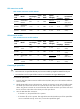
Table 53 Crossover cable pinouts
Pinout No. A
B
1 Orange/white Green/white
2 Orange Green
3 Green/white Orange/white
4 Blue Blue
5 Blue/white Blue/white
6 Green Orange
7 Brown/white Brown/white
8 Brown Brown
NOTE:
Strictly follow the pinouts in the above tables when identifyin
g
or makin
g
the two types of Ethernet cables;
otherwise, the communication quality might be affected.
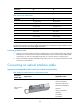
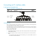
Connecting an Ethernet cable
1. Connect one end of an Ethernet cable to an Ethernet port on the module and the other end to the
Ethernet port on the peer device. Because the Ethernet port of the module supports MDI/MDIX
auto-sensing, you can use a straight-through cable or crossover cable to connect the port.
2. Examine the status of the LED of the Ethernet port after power-on. For the status of the LED, see the
relevant part in this manual.
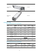
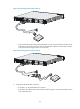
Connecting an optical interface cable
Appearances and applicable models of transceiver modules and optical fibers
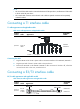
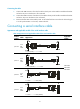
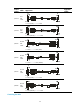
Table 54 Ethernet cable appearance and applicable models
Transceiver
module t
yp
e
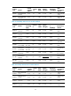
Appearance Applicable models
SFP transceiver
module
HIM-4GBP/HIM-8GBP
HIM-CL1P/HIM-CL2P
HIM-CLS1P/HIM-CLS2P
HIM-MSP2P/HIM-MSP4P
HIM-PS1P
HIM-AL1P/HIM-AL2P
HIM-RS2P
SAP-24GBP
SAP-48GBP