
HP 6600/HSR6600/HSR6800 Router Series Interface Module Guide

47
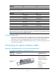
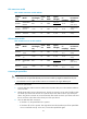
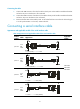
SFP+ transceiver module
Table 59 SFP+ transceiver module attributes
Product
code
Model
Central
wavelength(
nm)
Conne
ctor
Fiber
Mode
Optical
fiber(μm)
Transmissi
on
rate(Gb
p
s)
Max.
transmission
distance
JD092B
SFP-XG-SX-M
M850-A
850 LC MMF
50/125
10.31
300 m
(984.25 ft)
62.5/125
JD094B
SFP-XG-LX-S
M1310
1310 LC SMF 9/125 10.31
10 km (6.21
miles)
JG234A
SFP-XG-LH40
-SM1550
1550 LC SMF 9/125 10.31
40 km (24.86
miles)
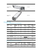
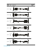
XFP transceiver module
Table 60 XFP transceiver module attributes
Product
code
Model
Central
wavelength(
nm)
Conne
ctor
Fiber
Mode
Optical
fiber(μm)
Transmissi
on
rate(Gb
p
s)
Max.
transmission
distance
JD107A
XFP-LH80-SM
1550
1550 LC SMF 9/125
9.95 to
10.7
80 km (49.71
miles)
JD108B
XFP-LX-SM13
10
1310 LC SMF 9/125 10.31
10 km (6.21
miles)
JD117B
XFP-SX-MM8
50
850 LC MMF
50/125
10.31
300 m
(984.25 ft)
62.5/125
JD121A
XFP-LH40-SM
1550-F1
1550 LC SMF 9/125
9.95 to
10.7
40 km (24.86
miles)
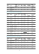
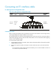
Connecting an optical fiber
CAUTION:
• Never stare into an open fiber Ethernet port, because invisible rays might be emitted from the port.
• Cover the dust cover if no optical fiber connector is connected to the copper Ethernet port.
To connect an optical fiber:
1. Insert the SFP/SFP+/XFP transceiver module to the SFP/SFP+/XFP port on the interface module or
service module.
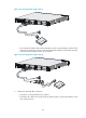
2. Identify the Rx and Tx ports on the transceiver. Plug the LC connector at one end of one fiber cable
into the Rx port of the router and the LC connector at the other end into the Tx port of the peer
device. Plug the LC connector at one end of another fiber cable into the Tx port of the router and
the LC connector at the other end to the Rx port of the peer device.
3. View the LINK LED after connection.
{ If the LED is on, the optical fiber link is present.
{ If the LED is off, no link is present. This might be because the TX and Rx port of the optical fiber
are not connected correctly. In this case, connect the optical fiber again.