
HP 6600/HSR6600/HSR6800 Router Series Interface Module Guide

50
NOTE:
• The Tx end of the cable must be connected to the Rx end of the peer device, and the Rx end of the cable
to the Tx end of the peer device.
• The coaxial cable connector and 75-ohm E1 trunk cable are optional accessories to be separately
ordered if needed.
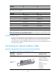
Connecting a T1 interface cable
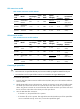
T1 cable appearance and applicable models
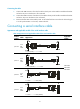
Table 62 T1 cable appearance and applicable models
Product
number
Cable Appearance
Applicable
models
JD639A
8-port T1
cable
1 x D68 < ---- > 8 x RJ45
MIM-8T1
MIM-8T1-F
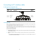
Connecting the cable
1. Plug the DB-68 end of the 8T1 splitter cable to the DB-68 interface of the MIM-8T1/MIM-8T1-F.
2. Plug the RJ-45 end of the 8T1 splitter cable to the peer device.
3. Examine the LINK LED on the MIM-8T1/MIM-8T1-F after connection. If the LED is off, a fault has
occurred on the link. In this case, examine the link.
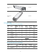
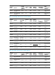
Connecting a E3/T3 interface cable
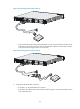
E3/T3 cable appearance and applicable models
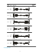
Table 63 E3/T3 cable appearance and applicable models
Product
number
Cable Appearance
Applicable
models
JD531A
JD533A
E3/T3
interfac
e cable
1 x BNS < ---- > 1 x SMB
MIM-1CE3
MIM-1CT3