
HP Comware 5 Debug Manual Vol 2

Field
Description
STAT state
XOT PVC state.
Init Interface: interface-name LCD: lcd-num
Interface and VC number through which the XOT PVC
connection was initiated.
Resp Interface: interface-name LCD: lcd-num
Destination interface and VC number of the XOT PVC
connection.
Win window-size WOut window-size
Sizes of the input window and the out-window on the
interface that initiated the XOT PVC connection.
IPS packet-size OPS packet-size
Maximum input packet size and output packet size
allowed on the interface that initiated the XOT PVC
connection.
Examples
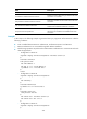
# The output in the following example is generated when you ping Router D from Router A under the
following conditions:
•
X.25 is enabled between Router A and Router B, and between Router C and Router D.
•
Router B and Router C are connected through their Ethernet interfaces.
•
The following operations are performed to enable Router A and Router D to communicate with each
other through TCP/IP:
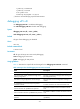
Configuration on Router A:
<Sysname> display current-configuration interface serial 2/0
#
interface Serial2/0
link-protocol x25
x25 x121-address 1
x25 map ip 1.1.1.2 x121-address 2
ip address 1.1.1.1 255.255.255.0
#
return
Configuration on Router B:
<Sysname> display current-configuration
#
x25 switching
#
interface Ethernet1/0
ip address 2.2.2.1 255.255.255.0
#
interface Serial 2/0
link-protocol x25 dce
#
x25 switch svc 1 interface Serial 2/0
x25 switch svc 2 xot 2.2.2.2
#
Configuration on Router C:
<Sysname> display current-configuration
#
322