
HP Comware 5 Debug Manual Vol 3

Field
Description
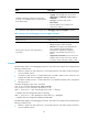
OSPF-BFD: Message type msg-type, Connect type
conn-type, Src IP Address src-ip, Src IFIndex if-index,
Dst IP Address dst-ip
Detailed OSPF BFD message information:
• msg-type—BFD message type, which can be
delete session, rcv BFD down, create session, or
disable BFD.
• conn-type—Connection type, which is
direct-connect.
• Source IP address, source interface, and
destination IP address.
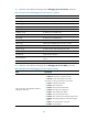
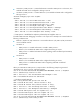
Table 2 describes output fields and messages for the debugging ospf event neighbor command.
Table 104 Output from the debugging ospf event neighbor command
Field
Description
OSPF process-id OSPF process ID.
Nbr nbr-ip Rcv nbr-event State original-state ->
current-state
Detailed information of neighbor state changes:
• nbr-ip—Neighbor interface IP address.
• nbr-event—Event triggering the HelloReceived,
Start, 2WayReceived, NegotiationDone,
ExchangeDone, BadLSReq, LoadingDone,
AdjOK?, 1-Way, KillNbr, Inactivity Timer, or
LLDown.
• original-state/current-state—Previous and current
neighbor state. The state can be Down, Attempt,
Init, 2-Way, ExStart, Exchange, Loading, or Full.
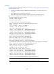
Examples
# Enable OSPF interface event debugging on Router A. The output in this example was created when the
following conditions exist:
•
Ethernet 1/0 (150.1.1.1/24) on Router A is connected to Ethernet 1/0 (150.1.1.2/24) on Router B
over a broadcast network.
•
On Router A, OSPF process 1 is created and area 0 is created in OSPF process 1. Ethernet 1/0 is
enabled with OSPF and is configured to belong to area 0.
•
On Router B, OSPF process 1 is created. Ethernet 1/0 is enabled with OSPF and is configured to
belong to area 0.
<RouterA> debugging ospf event interface
%Dec 12 09:24:58:978 2006 RouterA IFNET/4/UPDOWN:
Line protocol on the interface Ethernet1/0 is UP
OSPF 1: Intf 150.1.1.1 Rcv InterfaceUp State Down -> Waiting.
// Interface state was changed from Down to Waiting.
OSPF 1: Intf 150.1.1.1 Rcv BackupSeen State Waiting -> BackupDR.
// Interface state was changed from Waiting to BackupDR.
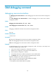
# Enable OSPF neighbor event debugging on Router A. The output in this example was created when the
following conditions exist:
•
Ethernet 1/0 (150.1.1.1/24) on Router A is connected to Ethernet 1/0 (150.1.1.2/24) on Router B
over a broadcast network.
141