HP HSR6800 Routers ACL and QoS Configuration Guide Part number: 5998-4495 Software version: HSR6800-CMW520-R3303P05 Document version: 6PW105-20140507
Legal and notice information © Copyright 2014 Hewlett-Packard Development Company, L.P. No part of this documentation may be reproduced or transmitted in any form or by any means without prior written consent of Hewlett-Packard Development Company, L.P. The information contained herein is subject to change without notice.
Contents Configuring ACLs ························································································································································· 1 Overview············································································································································································ 1 ACL categories ····································································································································
Introduction to priorities ········································································································································ 26 Priority mapping tables ········································································································································· 26 Priority mapping configuration tasks ··························································································································· 26 Configuring a pr
CBQ configuration example ································································································································ 65 Configuring RTP priority queuing ································································································································· 67 Configuration procedure ······································································································································ 67 RTP priority queuing confi
Configuring traffic redirecting ··································································································································· 95 Configuration guidelines ··············································································································································· 95 Configuration procedure ··············································································································································· 95 Tr
FR DE rule list ······················································································································································· 130 FR QoS configuration task list ····································································································································· 130 Creating and configuring an FR class ······················································································································· 130 Configurin
Network requirements ········································································································································· 160 Configuration procedures ··································································································································· 160 Support and other resources ·································································································································· 162 Contacting HP ··········
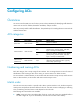
Configuring ACLs Overview An access control list (ACL) is a set of rules (or permit or deny statements) for identifying traffic based on criteria such as source IP address, destination IP address, and port number. ACLs are primarily used for traffic identification. The packet drop or forwarding decisions varies with the modules that use ACLs.
• auto—Sorts ACL rules in depth-first order. Depth-first ordering makes sure that any subset of a rule is always matched before the rule. Table 1 lists the sequence of tie breakers that depth-first ordering uses to sort rules for each type of ACL. Table 1 Sorting ACL rules in depth-first order ACL category IPv4 basic ACL IPv4 advanced ACL Sequence of tie breakers 1. VPN instance 2. More 0s in the source IP address wildcard (more 0s means a narrower IP address range) 3. Rule configured earlier 4.
Rule numbering step If you do not assign an ID to the rule you are creating, the system automatically assigns it a rule ID. The rule numbering step sets the increment by which the system automatically numbers rules. For example, the default ACL rule numbering step is 5. If you do not assign IDs to rules you are creating, they are automatically numbered 0, 5, 10, 15, and so on. The wider the numbering step, the more rules you can insert between two rules.
Task Remarks Configuring a basic ACL Required. Configure at least one task. Configuring an advanced ACL Basic ACLs and advanced ACLs are applicable to IPv4 and IPv6. Configuring an Ethernet frame header ACL Optional. Copying an ACL Applicable to IPv4 and IPv6. Enabling ACL acceleration for an IPv4 basic or IPv4 advanced ACL Optional. Configuring a time range You can create a maximum of 256 time ranges, each having a maximum of 32 periodic statements and 12 absolute statements.
Step Command Remarks By default, no ACL exists. Create an IPv4 basic ACL and enter its view. acl number acl-number [ name acl-name ] [ match-order { auto | config } ] Configure a description for the IPv4 basic ACL. description text Set the rule numbering step. step step-value 5. Create or edit a rule. rule [ rule-id ] { deny | permit } [ counting | fragment | logging | source { source-address source-wildcard | any } | time-range time-range-name | vpn-instance vpn-instance-name ] * 6.
Step Command Remarks 5. Create or edit a rule. rule [ rule-id ] { deny | permit } [ counting | fragment | logging | routing [ type routing-type ] | source { source-address source-prefix | source-address/source-prefix | any } | time-range time-range-name | vpn-instance vpn-instance-name ] * 6. Add or edit a rule comment. rule rule-id comment text Add or edit a rule range remark. rule [ rule-id ] remark text 7. By default, an IPv6 basic ACL does not contain any rule.
Step Command Remarks 5. Create or edit a rule.
Step Command Remarks Optional. Set the rule numbering step. step step-value 5. Create or edit a rule.
Step Command Remarks Configure a description for the Ethernet frame header ACL. description text Set the rule numbering step. step step-value 5. Create or edit a rule. rule [ rule-id ] { deny | permit } [ cos vlan-pri | counting | dest-mac dest-address dest-mask | { lsap lsap-type lsap-type-mask | type protocol-type protocol-type-mask } | source-mac source-address source-mask | time-range time-range-name ] * 6. Add or edit a rule comment.
Copying an IPv6 basic or IPv6 advanced ACL Step Command 1. Enter system view. system-view 2. Copy an existing IPv6 basic or IPv6 advanced ACL to create a new ACL. acl ipv6 copy { source-acl6-number | name source-acl6-name } to { dest-acl6-number | name dest-acl6-name } Enabling ACL acceleration for an IPv4 basic or IPv4 advanced ACL CAUTION: • ACL acceleration is not available for ACLs that contain a non-contiguous wildcard mask.
Task Command Remarks Display configuration and match statistics for IPv4 basic, IPv4 advanced, and Ethernet frame header ACLs (in standalone mode). display acl { acl-number | all | name acl-name } [ slot slot-number ] [ | { begin | exclude | include } regular-expression ] Available in any view. Display configuration and match statistics for IPv4 basic, IPv4 advanced, and Ethernet frame header ACLs (in IRF mode).
• Permit access from the Financial department to the database server only during working hours (from 8:00 to 18:00) on working days. • Deny access from any other department to the database server. Figure 1 Network diagram Financial database server 192.168.0.100/24 GE1/0/1 GE1/0/2 Device A GE1/0/4 GE1/0/3 President office Financial department Marketing department 192.168.1.0/24 192.168.2.0/24 192.168.3.
Pinging 192.168.0.100 with 32 bytes of data: Reply from 192.168.0.100: bytes=32 time=1ms TTL=255 Reply from 192.168.0.100: bytes=32 time<1ms TTL=255 Reply from 192.168.0.100: bytes=32 time<1ms TTL=255 Reply from 192.168.0.100: bytes=32 time<1ms TTL=255 Ping statistics for 192.168.0.100: Packets: Sent = 4, Received = 4, Lost = 0 (0% loss), Approximate round trip times in milli-seconds: Minimum = 0ms, Maximum = 1ms, Average = 0ms The output shows the database server can be pinged.
Figure 2 Network diagram Financial database server 1000::100/16 GE1/0/1 GE1/0/2 GE1/0/4 Device A GE1/0/3 President office Financial department Marketing department 1001::/16 1002::/16 1003::/16 Configuration procedure # Create a periodic time range from 8:00 to 18:00 on working days. system-view [RouterA] time-range work 8:0 to 18:0 working-day # Create an IPv6 advanced ACL numbered 3000 and configure three rules in the ACL.
Ping statistics for 1000::100: Packets: Sent = 4, Received = 4, Lost = 0 (0% loss), Approximate round trip times in milli-seconds: Minimum = 0ms, Maximum = 0ms, Average = 0ms The output shows that the database server can be pinged. # Ping the database server from a PC in the Marketing department during working hours. C:\> ping 1000::100 Pinging 1000::100 with 32 bytes of data: Destination net unreachable. Destination net unreachable. Destination net unreachable. Destination net unreachable.
QoS overview In data communications, Quality of Service (QoS) is a network's ability to provide differentiated service guarantees for diversified traffic in terms of bandwidth, delay, jitter, and drop rate. Network resources are scarce. The contention for resources requires that QoS prioritize important traffic flows over trivial ones. For example, when bandwidth is fixed, more bandwidth for one traffic flow means less bandwidth for the other traffic flows.
QoS techniques overview The QoS techniques include traffic classification, traffic policing, traffic shaping, rate limit, congestion management, and congestion avoidance. The following section briefly introduces these QoS techniques.
2. The QoS module takes various QoS actions on classified traffic as configured, depending on the traffic processing phase and network status. For example, you can configure the QoS module to perform traffic policing for incoming traffic, traffic shaping for outgoing traffic, congestion avoidance before congestion occurs, and congestion management when congestion occurs.
QoS configuration approaches QoS configuration approach overview You can configure QoS in the following approaches: • MQC approach • Non-MQC approach Some features support both approaches, but some support only one. MQC approach In the modular QoS configuration (MQC) approach, you configure QoS service parameters by using QoS policies. A QoS policy defines the shaping, policing, or other QoS actions to take on different classes of traffic. It is a set of class-behavior associations.
Figure 5 QoS policy configuration procedure Defining a class The system predefines some classes and defines general match criteria for them. A user-defined class cannot be named the same as a system-defined class. You can use these predefined classes when defining a policy. The system-defined classes include: The default class • default-class: Matches the default traffic. DSCP-based predefined classes • ef, af1, af2, af3, af4: Matches IP DSCP value ef, af1, af2, af3, af4, respectively.
By default, the operator of a class is AND. Create a class and enter class mapping view. 2. traffic classifier classifier-name [ operator { and | or } ] The operator of a class can be AND or OR. • AND—A packet is assigned to a class only when the packet matches all the criteria in the class. • OR—A packet is assigned to a class if it matches any of the criteria in the class. Configure match criteria. 3.
You cannot name a user-defined QoS policy the same as the system-defined QoS policy. To associate a class with a behavior in a policy: Step Command Remarks 1. Enter system view. system-view N/A 2. Create a policy and enter policy view. qos policy policy-name N/A 3. Associate a class with a behavior in the policy. classifier classifier-name behavior behavior-name Repeat this step to create more class-behavior associations.
Step 8. 9. Command Remarks Create the parent policy and enter parent policy view. qos policy policy-name N/A Associate the class with the behavior in the parent policy. classifier classifier-name behavior behavior-name N/A Applying the QoS policy You can apply a QoS policy to the following destinations: • An interface or PVC—The policy takes effect on the traffic sent or received on the interface or PVC.
Applying the QoS policy to online users You can apply a QoS policy to multiple online users. In one direction of each online user, only one policy can be applied. To modify a QoS policy already applied in a certain direction, remove the QoS policy application first. When you apply the QoS policy to online users, follow these guidelines: • You can only edit or remove the configurations in a disabled user profile. Disabling a user profile logs out the users that are using the user profile.
2. Apply the QoS policy to VLANs. qos vlan-policy policy-name vlan vlan-id-list { inbound | outbound } Displaying and maintaining QoS policies Task Command Remarks Display a specified class-behavior association in a specified policy or all class-behavior associations in a specified policy or in all policies. display qos policy { system-defined | user-defined } [ policy-name [ classifier classifier-name] ] [ | { begin | exclude | include } regular-expression ] Available in any view.
Configuring priority mapping This feature is supported only on SAP modules operating in bridge mode. Overview When a packet arrives, depending on your configuration, a device assigns a set of QoS priority parameters to the packet based on either a certain priority field carried in the packet or the port priority of the incoming port. This process is called "priority mapping." During this process, the device can modify the priority of the packet depending on device status.
In this approach, you can configure a port to look up a certain priority, 802.1p for example, in incoming packets, in the priority mapping tables. If no packet priority is trusted, the port priority of the incoming port is used. Changing port priority. • By default, all ports are assigned the port priority of zero. By changing the port priority of a port, you change the priority of the incoming packets on the port.
Configuring the trusted packet priority type for an interface or port group You can configure the router to trust a particular priority field carried in packets for priority mapping on a port or port group. To configure the trusted packet priority type on an interface or port group: Step 1. Enter system view. Command Remarks system-view N/A Use one of the commands. • Enter interface view: 2. Enter interface view or port group view.
Task Command Remarks Display priority mapping table configuration. display qos map-table [ dot1p-dp | dot1p-lp | dscp-dot1p | dscp-dp | dscp-dscp ] [ | { begin | exclude | include } regular-expression ] Available in any view. Display the trusted packet priority type on a port. display qos trust interface [ interface-type interface-number ] [ | { begin | exclude | include } regular-expression ] Available in any view.
# Assign port priorities to GigabitEthernet 1/0/1 and GigabitEthernet 1/0/2. Make sure that the priority of GigabitEthernet 1/0/1 is higher than GigabitEthernet 1/0/2, and no trusted packet priority type is configured on GigabitEthernet 1/0/1 or GigabitEthernet 1/0/2.
Figure 7 Network diagram Internet Host Host Server Server GE1/0/5 Management deparment GE1/0/3 GE1/0/1 GE1/0/4 Data server R&D department GE1/0/2 Router Host Server Mail server Marketing department Public servers Configuration procedure 1. Configure trusting port priority: # Set the port priority of GigabitEthernet 1/0/1 to 3.
[Router-maptbl-dot1p-lp] quit 32
Configuring traffic policing, traffic shaping, and rate limit Overview Traffic policing traffic shaping, and rate limit are QoS techniques that help assign network resources, such as bandwidth. They increase network performance and user satisfaction. For example, you can configure a flow to use only the resources committed to it in a certain time range. This avoids network congestion caused by burst traffic.
• CBS—Size of bucket C, which specifies the transient burst of traffic that bucket C can forward. • Excess burst size (EBS)—Size of bucket E, which specifies the transient burst of traffic that bucket E can forward. Figure 8 Two-bucket structure Figure 8 shows the two-bucket structure. CBS is implemented with bucket C, and EBS with bucket E. In each evaluation, packets are measured against the following bucket scenarios: • If bucket C has enough tokens, packets are colored green.
• Dropping the packet if the evaluation result is "excess." • Forwarding the packet with its IP precedence re-marked if the evaluation result is "conforming." • Delivering the packet to next-level traffic policing with its IP precedence re-marked if the evaluation result is "conforming." • Entering the next-level policing (you can set multiple traffic policing levels each focused on specific objects). Traffic shaping Traffic shaping supports shaping the inbound traffic and the outbound traffic.
Rate limit Rate limit supports controlling the rate of inbound traffic and outbound traffic. The rate limit of a physical interface specifies the maximum rate for forwarding packets (including critical packets). Rate limit also uses token buckets for traffic control. With rate limit configured on an interface, all packets to be sent through the interface are handled by the token bucket for rate limiting. If enough tokens are in the token bucket, packets can be forwarded.
Task Remarks Configuring the rate limit Configuring traffic policing Configure traffic policing in either policy approach or non-policy approach. If traffic policing is configured in both the policy approach and non-policy approach, the configuration in policy approach takes effect. Configuring traffic policing by using the policy approach Step Command Remarks 1. Enter system view. system-view N/A 2. Create a class and enter class view.
Configuring traffic policing by using the non-policy approach Configuring CAR-list-based traffic policing Step 1. 2. Command Remarks Enter system view. system-view N/A Configure a CAR list. qos carl carl-index { precedence precedence-value | mac mac-address | mpls-exp mpls-exp-value | dscp dscp-list | { destination-ip-address | source-ip-address } { subnet ip-address mask-length | range start-ip-address to end-ip-address } [ per-address [ shared-bandwidth ] ] } Configure rules on the CAR list.
3. Configure a CAR action for all traffic on the interface or port group. qos car { inbound | outbound } any cir committed-information-rate [ cbs committed-burst-size [ ebs excess-burst-size ] ] [ green action ] [ red action ] Configuring GTS GTS for software forwarding does not support IPv6. Do not configure GTS on a main interface and its subinterfaces at the same time. Configuring GTS by using the policy approach Step Command Remarks 1. Enter system view. system-view N/A 2.
• ACL-based GTS—Sets GTS parameters for the traffic matching the specific ACL. By specifying multiple ACLs, you can set GTS parameters for different classes of traffic. • GTS for all traffic—Configures GTS parameters for all traffic. Configuring ACL-based GTS Step Command 1. Enter system view. system-view 2. Defining an ACL. See "Configuring ACLs." 3. Enter interface view. interface interface-type interface-number 4. Configure ACL-based GTS on the interface.
Step 1. Enter system view. Command Remarks system-view N/A Use one of the commands. 2. Enter interface view. interface interface-type interface-number 3. Configure the rate limit for the interface or port group. qos lr inbound cir committed-information-rate [ cbs committed-burst-size [ ebs excess-burst-size ] ] Settings in interface view take effect on the current interface. Settings in port group view take effect on all ports in the port group.
Task Command Remarks Display interface GTS configuration information. display qos gts interface [ interface-type interface-number ] [ | { begin | exclude | include } regular-expression ] Available in any view. Display interface rate limit configuration information. display qos lr interface [ interface-type interface-number ] [ | { begin | exclude | include } regular-expression ] Available in any view.
Figure 13 Network diagram Configuration procedure 1. Configure Router A: # Configure GTS on GigabitEthernet 1/0/3, shaping the packets when the sending rate exceeds 500 kbps to decrease the packet loss rate of GigabitEthernet 1/0/1 of Router B. system-view [RouterA] interface gigabitethernet 1/0/3 [RouterA-GigabitEthernet1/0/3] qos gts any cir 500 [RouterA-GigabitEthernet1/0/3] quit # Configure ACLs to permit the packets from Server and Host A.
# Configure a CAR policy on GigabitEthernet 1/0/2 to limit the sending rate to 1 Mbps and drop the excess packets.
Configuring congestion management Overview Causes, impacts, and countermeasures of congestion Congestion occurs on a link or node when traffic size exceeds the processing capability of the link or node. It is typical of a statistical multiplexing network and can be caused by link failures, insufficient resources, and various other causes. Figure 15 shows some common congestion scenarios.
FIFO Figure 16 FIFO queuing As shown in Figure 16, the first in first out (FIFO) uses a single queue and does not classify traffic or schedule queues. FIFO delivers packets depending on their arrival order, with the one arriving earlier scheduled first. The only concern of FIFO is queue length, which affects delay and packet loss rate. On a device, resources are assigned for packets depending on their arrival order and load status of the device. The best-effort service model uses FIFO queuing.
Priority queuing schedules the four queues in the descending order of priority. It sends packets in the queue with the highest priority first. When the queue with the highest priority is empty, it sends packets in the queue with the second highest priority. In this way, you can assign the mission-critical packets to the high priority queue to make sure that they are always served first.
WFQ Figure 19 Weighted fair queuing (WFQ) Before WFQ is introduced, make sure that you have understood fair queuing (FQ). FQ is designed for fairly allocating network resources to reduce delay and jitter of each traffic flow as possible. In an attempt to balance the interests of all parties, FQ follows these principles: • Different queues have fair dispatching opportunities for delay balancing among streams.
CBQ Figure 20 CBQ Class-based queuing (CBQ) extends WFQ by supporting user-defined classes. When network congestion occurs, CBQ uses user-defined traffic match criteria to enqueue packets. Before that, congestion avoidance actions, such as tail drop or WRED and bandwidth restriction check, are performed before packets are enqueued. When being dequeued, packets are scheduled by WFQ. CBQ provides the following queues: • Emergency queue—Enqueues emergent packets.
• Match packets with priority classes in the configuration order. • Match packets with other classes in the configuration order. • Match packets with classification rules in a class in the configuration order. RTP priority queuing Real-time transport protocol (RTP) priority queuing is a simple queuing technique designed to guarantee QoS for real-time services (including voice and video services).
Table 4 Congestion management technique comparison Type Number of queues Advantages Disadvantages • All packets are treated equally. The available bandwidth, delay and drop probability are determined by the arrival order of packets. • No need to configure, easy FIFO 1 to use. • Easy to operate, low delay.
Type Number of queues Advantages Disadvantages • Flexible traffic classification based on various rules and differentiated queue scheduling mechanisms for EF, AF and BE services. • Highly precise bandwidth guarantee and queue scheduling on the basis of AF service weights for various AF services. CBQ Configurable (0 to 64) • Absolutely preferential queue scheduling for the EF service to meet the delay requirement of real-time data. The system overheads are large.
By default: • The FIFO queue length is Configure the FIFO queue size. 3. qos fifo queue-length queue-length 75 for tunnel interfaces, aggregate interfaces, and HDLC link bundle interfaces. • The FIFO queue length is 1024 for other interfaces.
2. Configure a PQ list. qos pql pql-index protocol ip [ queue-key key-value ] queue { bottom | middle | normal | top } N/A Optional. This command specifies the queue to which unmatched packets are assigned. 3. Specify the default queue for the PQ list. qos pql pql-index default-queue { bottom | middle | normal | top } 4. Set the queue size. qos pql pql-index queue { bottom | middle | normal | top } queue-length queue-length Optional. 5. Enter interface view.
Configuration procedure Configure Router A: # Configure ACLs to match the packets from Server and Host A, respectively. [RouterA] acl number 2001 [RouterA-acl-basic-2001] rule permit source 1.1.1.1 0.0.0.0 [RouterA] acl number 2002 [RouterA-acl-basic-2002] rule permit source 1.1.1.2 0.0.0.0 # Configure a PQ list that assigns the packets from Server to the top queue and those from Host A to the bottom queue when congestion occurs.
6. Enter interface view. interface interface-type interface-number N/A 7. Apply the CQ list to the interface. qos cq cql cql-index By default, FIFO applies. 8. Display CQ list configuration on an interface. display qos cq interface [ interface-type interface-number ] [ | { begin | exclude | include } regular-expression ] Display the configuration of a CQ list. display qos cql [ cql-index ] [ | { begin | exclude | include } regular-expression ] 9. Optional. Available in any view. Optional.
3. Configure WFQ. qos wfq [ dscp | precedence ] [ queue-length max-queue-length [ queue-number total-queue-number ] ] 4. Display interface WFQ configuration information. display qos wfq interface [ interface-type interface-number ] [ | { begin | exclude | include } regular-expression ] By default, FIFO applies. Optional. Available in any view. WFQ configuration example Network requirements Configure WFQ on Serial 2/1/1, setting the maximum queue size to 100, and the total number of queues to 512.
MPLS EXP-based predefined classes • mpls-exp0, mpls-exp1, …mpls-exp7—Matches MPLS EXP value 0, 1, …7, respectively. Predefined traffic behaviors The system predefines some traffic behaviors and defines QoS features for them. • ef—Assigns a class of packets to the EF queue and assigns 20% of the available interface/PVC bandwidth to the class of packets. • af—Assigns a class of packets to the AF queue and assigns 20% of the available interface/PVC bandwidth to the class of packets.
To reference both the queue ef command and the queue af command in a policy, you must configure them in the same unit (either bandwidth or percentage). If not, your referencing attempts will fail. • To configure AF and the minimum guaranteed bandwidth: Step Command Remarks 1. Enter system view. system-view N/A 2. Create a traffic behavior and enter traffic behavior view. traffic behavior behavior-name The specified behavior name cannot be the name of any system-defined behavior. 3.
Configuring the maximum queue size Configure the maximum queue size and use tail drop. When low-priority services preempt the bandwidth for the AF service, you can increase the queue size for the AF service. To configure the maximum queue size: Step Command Remarks 1. Enter system view. system-view N/A 2. Create a traffic behavior and enter traffic behavior view. traffic behavior behavior-name The specified traffic behavior name cannot be the name of any system-defined behavior. 3.
2. Create a traffic behavior and enter traffic behavior view. traffic behavior behavior-name The specified traffic behavior name cannot be the name of any system-defined behavior. 3. Configure the exponent for WRED to calculate the average queue size. wred weighting-constant exponent The default exponent is 9.
Configure the lower limit, upper limit and drop probability denominator for an IP precedence value in WRED. 3. wred ip-precedence precedence low-limit low-limit high-limit high-limit [ discard-probability discard-prob ] N/A Defining a QoS policy You associate a behavior with a class in a QoS policy. Each behavior includes a set of actions, such as queue scheduling (EF, AF, and WFQ), traffic policing, traffic shaping, WRED, and traffic marking.
Step 1. Enter system view. Command Remarks system-view N/A • Enter interface view: 2. Enter interface view or PVC view. interface interface-type interface-number • Enter PVC view: a. interface atm interface-number Settings in interface view take effect on the current interface. Settings in PVC view take effect on the current PVC. b. pvc vpi/vci 3. Apply a policy to the interface or PVC.
Step Command 1. Enter system view. system-view 2. Enter interface view. interface interface-type interface-number 3. Configure the maximum available bandwidth of the interface. qos max-bandwidth bandwidth If no maximum available bandwidth is configured for an interface, the bandwidth used for CBQ calculation is as follows: • For a physical interface, the actual baud rate or rate applies.
Displaying and maintaining CBQ Task Command Remarks Display class configuration information. display traffic classifier { system-defined | user-defined } [ classifier-name ] [ | { begin | exclude | include } regular-expression ] Available in any view. Display traffic behavior configuration information. display traffic behavior { system-defined | user-defined } [ behavior-name ] [ | { begin | exclude | include } regular-expression ] Available in any view.
Figure 23 Network diagram Router D Router C Ethernet Ethernet AF11 S1/1/1 1.1.1.1/24 S1/1/1 1.1.1.2/24 AF21 EF Router B Router A Configuration procedure Configure Router A: # Define three classes to match the IP packets with the DSCP values AF11, AF21, and EF, respectively.
# Apply the QoS policy to the outgoing traffic of interface Serial 1/1/1. [RouterA] interface serial 1/1/1 [RouterA-Serial1/1/1] ip address 1.1.1.1 255.255.255.0 RouterA-Serial1/1/1] qos apply policy dscp outbound The configuration enables EF traffic to be forwarded preferentially when congestion occurs. Configuring RTP priority queuing Configuration procedure To configure RTP priority queuing: Step Command Remarks 1. Enter system view. system-view N/A 2. Enter interface view.
[Sysname-Serial1/1/1] qos rtpq start-port 16384 end-port 32767 bandwidth 64 Configuring QoS tokens Because the upper layer protocol TCP provides traffic control, CQ and WFQ might become invalid during FTP transmission. QoS tokens can solve this problem. The token feature of QoS provides a flow control mechanism for underlying-layer queues. This feature can control the number of packets sent to the interface underlying-layer queues based on the number of tokens.
Configuring packet information pre-extraction On a logical interface, such as a tunnel, RPR logical, Layer 3 aggregate, or HDLC link bundle interface, if the interface has processed the incoming IP packets, for example, if the tunnel interface has used GRE to encapsulate packets, the GRE-encapsulated packets enter the QoS module for processing. As a result, the QoS module cannot get the IP information of the original packets.
Configuring hardware congestion management This feature is supported only on SAP modules operating in bridge mode. Overview Causes, impacts, and countermeasures Network congestion degrades service quality on a traditional network. Congestion is a situation where the forwarding rate decreases due to insufficient resources, resulting in extra delay. Congestion is more likely to occur in complex packet switching circumstances. Figure 24 shows two common cases.
SP queuing SP queuing is designed for mission-critical applications that require preferential service to reduce the response delay when congestion occurs. Figure 25 SP queuing In Figure 25, SP queuing classifies eight queues on a port into eight classes, numbered 7 to 0 in descending priority order. SP queuing schedules the eight queues in the descending order of priority. SP queuing sends packets in the queue with the highest priority first.
Figure 26 WRR queuing Queue 0 Weight 1 Packets to be sent through this port Queue 1 Weight 2 Sent packets Interface …… Queue N-2 Weight N-1 Queue scheduling Packet classification Sending queue Queue N-1 Weight N Assume a port provides eight output queues. WRR assigns each queue a weight value (represented by w7, w6, w5, w4, w3, w2, w1, or w0) to decide the proportion of resources assigned to the queue.
WFQ queuing Figure 27 WFQ queuing WFQ is similar to WRR. They both support scheduling weights in queue length, and can work with SP scheduling together. The difference is that WRR enables you to set the maximum time a packet waits in queue, but WFQ enables you to set guaranteed bandwidth a WFQ queue can get during congestion. CBQ CBQ provides one FIFO queue for each user-defined class to buffer traffic of the class.
Configure queue scheduling in a QoS policy, as described in Configuring CBQ. • Complete the following tasks to achieve hardware congestion management: Task Remarks Configuring per-queue hardware congestion management Configuring SP queuing Optional. Configure group-based WRR queuing Optional. Configuring WFQ queuing Optional. Configuring CBQ Optional. Configuring per-queue hardware congestion management Configuring SP queuing Configuration procedure Step 1. 2. Enter system view.
Configure group-based WRR queuing When a WRR queue is configured on an interface, WRR queuing is enabled on the interface, and other queues on the interface use the default WRR scheduling value and are assigned to the default WRR priority group. Configuration procedure Step Enter system view. 1. Command Remarks system-view N/A • Enter interface view: Enter interface view or port group view. 2.
Optional. 5. Assign a queue to the SP group. qos wrr queue-id group sp 6. Display WRR queuing configuration information. display qos wrr interface [ interface-type interface-number ] [ | { begin | exclude | include } regular-expression ] Queues in the SP group are scheduled by using the SP mechanism. Optional. Available in any view. Configuration example 1. Network requirements { Enable WRR queuing on interface GigabitEthernet 1/0/1. { Assign queue 0 and queue 1 to the SP group. { { 2.
5. 6. Configure the minimum guaranteed bandwidth for a WFQ queue. qos bandwidth queue queue-id min bandwidth-value Display WFQ queuing configuration. display qos wfq interface [ interface-type interface-number ] [ | { begin | exclude | include } regular-expression ] Optional. WFQ queuing is only applicable to Layer 2 interfaces. Optional. Available in any view. Configuration example 1.
Step Command Remarks 1. Enter system view. system-view N/A 2. Create a class and enter class view. traffic classifier classifier-name [ operator { and | or } ] By default, the and keyword is used, and the relation between match criteria is logical AND. 3. Configure match criteria. if-match [ not ] match-criteria N/A Defining a traffic behavior Configuring AF and the minimum guaranteed bandwidth Step Command Remarks 1. Enter system view. system-view N/A 2.
2. Create a traffic behavior and enter traffic behavior view. The specified traffic behavior name cannot be the name of any system-defined behavior. traffic behavior behavior-name • dscp—Uses the DSCP value for calculating 3. Configure a WRED drop action. the drop probability for a packet. wred [ dscp | ip-precedence ] • ip-precedence—Uses the IP precedence value for calculating the drop probability for a packet. This keyword is used by default.
Apply a policy to the interface or PVC. 3. qos apply policy policy-name { inbound | outbound } On some cards, QoS policies can be applied but cannot take effect due to limited system resources. In this case, you can adjust related parameters (for example, reducing the number of queues) according to system prompt and then apply a QoS policy again. Displaying and maintaining CBQ Task Command Remarks Display class configuration information.
Figure 28 Network diagram Configuration procedure Before performing the configuration, make sure that: • Router C and Router D can reach each other through Router A and Router B. • The DSCP field of the traffic has been set before it enters Router A. Configure Router A: # Define three classes to match the IP packets with DSCP AF11, AF21 and EF, respectively.
[RouterA-qospolicy-dscp] classifier af21_class behavior af21_behav [RouterA-qospolicy-dscp] classifier ef_class behavior ef_behav [RouterA-qospolicy-dscp] quit # Apply the QoS policy to the outgoing traffic of ATM PVC ATM 1/0. [RouterA] interface 2/1/1 [RouterA-atm2/1/1] ip address 1.1.1.1 255.255.255.0 [RouterA-atm2/1/1] pvc qostest 0/40 [RouterA-atm-pvc-atm2/1/1-0/40-qostest] qos apply policy dscp outbound When congestion occurs, Router A will forward EF traffic preferentially.
Configuring congestion avoidance Overview Avoiding congestion before it occurs is a proactive approach to improving network performance. As a flow control mechanism, congestion avoidance actively monitors network resources (such as queues and memory buffers), and drops packets when congestion is expected to occur or deteriorate. Compared with end-to-end flow control, this flow control mechanism controls the load of more flows in a device.
With WFQ queuing used, you can set the exponent for average queue size calculation, upper threshold, lower threshold, and drop probability for packets with different precedence values to provide differentiated drop policies. With FIFO queuing, PQ, or CQ used, you can set the exponent for average queue size calculation, upper threshold, lower threshold, and drop probability for each queue to provide differentiated drop policies for different classes of packets.
• The exponent used for average queue size calculation—The bigger the exponent is, the less sensitive the average queue size is to real-time queue size changes. • Denominator for drop probability calculation—The bigger the denominator is, the smaller the calculated drop probability is. Configuring WRED on an interface Configuration procedure Before configuring the qos wred enable command, you must enable WFQ queuing on the interface. To configure WRED on an interface: Step Command Remarks 1.
[Sysname-GigabitEthernet1/0/1] qos wred ip-precedence enable # Set the following parameters for packets with IP precedence 3: lower threshold 20, upper threshold 40, and drop probability denominator 15. [Sysname-GigabitEthernet1/0/1] qos wred ip-precedence 3 low-limit 20 high-limit 40 discard-probability 15 # Set the exponential factor for the average queue size calculation to 6.
# Enter system view. system-view # Configure a queue-based WRED table. [Sysname] qos wred queue table queue-table1 [Sysname-wred-table-queue-table1] quit # Enter interface view. [Sysname] interface gigabitethernet 1/0/1 # Apply the queue-based WRED table to GigabitEthernet 1/0/1. [Sysname-GigabitEthernet1/0/1] qos wred apply queue-table1 Displaying and maintaining WRED Task Command Remarks Display the WRED configuration on an interface/PVC or all interfaces/PVCs.
Figure 30 Network diagram Configuration procedure # Configure ACLs to match the packets from Server, Telephone, Host A, and Host B, respectively. system-view [Router] acl number 2001 [Router-acl-basic-2001] rule 1 permit source 10.1.1.1 0 [Router-acl-basic-2001] quit [Router] acl number 2002 [Router-acl-basic-2002] rule 2 permit source 10.1.1.2 0 [Router-acl-basic-2002] quit [Router] acl number 2003 [Router-acl-basic-2003] rule 3 permit source 10.1.1.
[Router] traffic behavior behavior3 [Router-behavior-behavior3] remark ip-precedence 3 [Router-behavior-behavior3] quit [Router] traffic behavior behavior4 [Router-behavior-behavior4] remark ip-precedence 2 [Router-behavior-behavior4] quit [Router] qos policy aa [Router-qospolicy-aa] classifier class1 behavior behavior1 [Router-qospolicy-aa] classifier class2 behavior behavior2 [Router-qospolicy-aa] classifier class3 behavior behavior3 [Router-qospolicy-aa] classifier class4 behavior behavior4 [Router-qospo
Configuring traffic filtering You can filter in or filter out a class of traffic by associating the class with a traffic filtering action. For example, you can filter packets sourced from a specific IP address according to network status. Configuration procedure To configure traffic filtering: Step Command Remarks 1. Enter system view. system-view N/A 2. Create a class and enter class view. traffic classifier classifier-name [ operator { and | or } ] N/A 3. Configure match criteria.
Traffic filtering configuration example Network requirements As shown in Figure 31, configure traffic filtering to filter the packets with source port not being 21, and received on GigabitEthernet 1/0/1. Figure 31 Network diagram Configuration procedure # Create advanced ACL 3000, and configure a rule to match packets whose source port number is not 21.
Configuring priority marking Priority marking sets the priority fields or flag bits of packets to modify the priority of traffic. For example, you can use priority marking to set IP precedence or DSCP for a class of IP traffic to change its transmission priority in the network. To configure priority marking, you can associate a class with a behavior configured with the priority marking action to set the priority fields or flag bits of the class of packets.
Step Command Remarks 16. Display the priority marking configuration. display traffic behavior { system-defined | user-defined } [ behavior-name ] [ | { begin | exclude | include } regular-expression ] Optional. Available in any view.
# Create advanced ACL 3002, and configure a rule to match packets with destination IP address 192.168.0.3. [Router] acl number 3002 [Router-acl-adv-3002] rule permit ip destination 192.168.0.3 0 [Router-acl-adv-3002] quit # Create a class named classifier_dbserver, and use ACL 3000 as the match criterion in the class.
Configuring traffic redirecting This feature is supported only on SAP modules operating in bridge mode. Traffic redirecting is the action of redirecting the packets matching the specific match criteria to a certain location for processing. The following redirect actions are supported: • Redirecting traffic to the CPU—Redirects packets that require processing by the CPU to the CPU. • Redirecting traffic to an interface—Redirects packets that require processing by an interface to the interface.
Step 9. Associate the class with the traffic behavior in the QoS policy. 10. Return to system view. Command Remarks classifier classifier-name behavior behavior-name N/A quit N/A • Applying the QoS policy to an interface or Choose one of the application destinations as needed. PVC 11. Apply the QoS policy.
[RouterA] acl number 2001 [RouterA-acl-basic-2001] rule permit source 2.1.1.2 0 [RouterA-acl-basic-2001] quit # Create a class named classifier_1, and use ACL 2000 as the match criterion in the class. [RouterA] traffic classifier classifier_1 [RouterA-classifier-classifier_1] if-match acl 2000 [RouterA-classifier-classifier_1] quit # Create a class named classifier_2, and use ACL 2001 as the match criterion in the class.
Configuring class-based accounting Class-based accounting collects statistics (in number of packets or bytes) on a per-traffic class basis. For example, you can define the action to collect statistics for traffic sourced from a certain IP address. By analyzing the statistics, you can determine whether anomalies have occurred and what action to take. Configuration procedure To configure class-based accounting: Step Command Remarks 1. Enter system view. system-view N/A 2.
Class-based accounting configuration example Network requirements As shown in Figure 34, configure class-based accounting to collect statistics for traffic sourced from 1.1.1.1/24 and received on GigabitEthernet 1/0/1. Figure 34 Network diagram Configuration procedure # Create basic ACL 2000, and configure a rule to match packets with source IP address 1.1.1.1. system-view [Router] acl number 2000 [Router-acl-basic-2000] rule permit source 1.1.1.
Operator: AND Rule(s) : If-match acl 2000 Behavior: behavior_1 Accounting Enable: 28529 (Packets) 100
Configuring QPPB Overview The QoS Policy Propagation Through the Border Gateway Protocol (QPPB) feature enables you to classify IP packets based on BGP community lists, prefix lists, and BGP AS paths. The idea of QPPB is that the BGP route sender pre-classifies routes before advertising them, and the BGP route receiver sets the IP precedence and QoS-local ID for the routes and takes appropriate QoS actions on the packets that match the routes.
Task Remarks Configuring a QoS policy Required. Applying the QoS policy to an interface Required. Configuring the route sender Configure the BGP route sender to set route attributes for routes before advertising them. Configuring basic BGP functions For more information, see Layer 3—IP Routing Configuration Guide and Layer 3—IP Routing Command Reference. Creating a routing policy Configure a routing policy to classify routes and set route attributes for the route classes.
Step Enable QPPB on the interface. 3. Command Remarks bgp-policy { destination | source } { ip-prec-map | ip-qos-map } * The command applies to only incoming traffic. Configuring a QoS policy The classes in the QoS policy use the IP precedence and QoS-local ID set by the routing policy as match criteria. Applying the QoS policy to an interface Step Command Remarks 1. Enter system view. system-view N/A 2. Enter interface view.
2. Configure Router A: # Configure a BGP connection to Router B, and add the network 1.1.1.0/8 to the BGP routing table. system-view [RouterA] bgp 1000 [RouterA-bgp] peer 168.1.1.2 as-number 2000 [RouterA-bgp] network 1.1.1.0 255.255.255.0 [RouterA-bgp] quit 3. Configure Router B: # Configure a BGP connection to Router A, apply the routing policy qppb to routes from the peer 168.1.1.1, and add the network 2.2.2.0/8 to the BGP routing table.
Destination: 1.1.1.0/24 Protocol: BGP Process ID: 0 Preference: 255 Cost: 0 IpPrecedence: 1 QosLcId: 3 NextHop: 168.1.1.1 BkNextHop: 0.0.0.0 Interface: Serial 2/1/1 BkInterface: RelyNextHop: 0.0.0.0 Neighbor : 168.1.1.1 Tunnel ID: 0x0 Label: NULL State: Active Adv GotQ Age: 00h00m45s Tag: 0 # Display the QoS policy configuration on port Serial 2/1/1 of Router B.
Figure 36 Network diagram Device Interface IP address Device Interface IP address Router A GE1/0/1 192.168.1.2/24 Router B GE1/0/1 167.1.1.2/24 GE1/0/2 167.1.1.1/24 S2/1/1 168.1.1.2/24 Router C GE1/0/1 169.1.1.2/24 GE1/0/2 169.1.1.1/24 S2/1/1 168.1.1.1/24 GE1/0/1 192.168.2.2/24 Router D Configuration procedure 1. Configure IP addresses for each interface. (Details not shown.) 2. Configure Router A: # Configure a BGP connection.
[RouterB-mpls] quit [RouterB] mpls ldp [RouterB-mpls-ldp] quit # Configure OSPF. [RouterB] ospf [RouterB-ospf-1] area 0 [RouterB ospf-1-area-0.0.0.0] network 1.1.1.1 0.0.0.0 [RouterB ospf-1-area-0.0.0.0] network 168.1.1.0 0.0.0.255 [RouterB ospf-1-area-0.0.0.0] quit [RouterB-ospf-1] quit # Bind interface GigabitEthernet 1/0/1 to VPN instance vpn1. [RouterB] interface gigabitethernet 1/0/1 [RouterB-GigabitEthernet1/0/1] ip binding vpn-instance vpn1 [RouterB-GigabitEthernet1/0/1] ip address 167.1.1.
[RouterC] mpls lsr-id 2.2.2.2 [RouterC] mpls [RouterC-mpls] quit [RouterC] mpls ldp [RouterC-mpls-ldp] quit # Configure OSPF. [RouterC] ospf [RouterC-ospf-1] area 0 [RouterC ospf-1-area-0.0.0.0] network 2.2.2.2 0.0.0.0 [RouterC ospf-1-area-0.0.0.0] network 168.1.1.0 0.0.0.255 [RouterC ospf-1-area-0.0.0.0] quit [RouterC-ospf-1] quit # Configure a QoS policy.
6. Verify the configuration: # Check whether the related routes on Router A take effect. [RouterA] display ip routing-table Routing Tables: Public Destinations : 7 Destination/Mask Proto 127.0.0.0/8 127.0.0.1/32 Routes : 7 Pre Cost NextHop Interface Direct 0 0 127.0.0.1 InLoop0 Direct 0 0 127.0.0.1 InLoop0 167.1.1.0/24 Direct 0 0 167.1.1.1 GE1/0/2 167.1.1.1/32 Direct 0 0 127.0.0.1 InLoop0 192.168.1.0/24 Direct 0 0 192.168.1.2 GE1/0/1 192.168.1.2/32 Direct 0 0 127.0.0.
Destination/Mask Proto Cost NextHop Interface 127.0.0.0/8 Direct 0 Pre 0 127.0.0.1 InLoop0 127.0.0.1/32 Direct 0 0 127.0.0.1 InLoop0 169.1.1.0/24 Direct 0 0 169.1.1.2 GE1/0/1 169.1.1.2/32 Direct 0 0 127.0.0.1 InLoop0 192.168.1.0/24 BGP 255 0 1.1.1.1 NULL0 192.168.2.0/24 BGP 255 0 169.1.1.1 GE1/0/1 # Check whether the related routes on Router D take effect.
Classifier: default-class Matched : 0(Packets) 0(Bytes) 5-minute statistics: Forwarded: 0/0 (pps/bps) Dropped : 0/0 (pps/bps) Rule(s) : If-match any Behavior: be -noneClassifier: Matched : 0(Packets) 0(Bytes) 5-minute statistics: Forwarded: 0/0 (pps/bps) Dropped : 0/0 (pps/bps) Operator: AND Rule(s) : If-match qos-local-id 1023 Behavior: qppb-l3vpn Committed Access Rate: CIR 2000 (kbps), CBS 125000 (byte), EBS 0 (byte) Green Action: pass Red Action: discard Green : 0(Packets) 0(Bytes) Red : 0(Packets)
[RouterA-bgp-af-ipv6] network 1:: 64 [RouterA-bgp-af-ipv6] quit [RouterA-bgp] quit 3. Configure Router B: # Configure BGP. system-view [RouterB] bgp 2000 [RouterB-bgp] ipv6-family [RouterB-bgp-af-ipv6] peer 168::1 as-number 1000 [RouterB-bgp-af-ipv6] peer 168::1 route-policy qppb import [RouterB-bgp-af-ipv6] network 2:: 64 [RouterB-bgp-af-ipv6] quit [RouterB-bgp] quit # Configure a routing policy.
Destination: 1::1/128 Protocol : Direct NextHop : ::1 Preference: 0 Interface : InLoop0 Cost : 0 Destination: 2::/64 Protocol : BGP4+ NextHop : 168::2 Preference: 255 Interface : S2/1/1 Cost : 0 Destination: 168::/64 Protocol : Direct NextHop : 168::1 Preference: 0 Interface : S2/1/1 Cost : 0 Destination: 168::1/128 Protocol : Direct NextHop : ::1 Preference: 0 Interface : InLoop0 Cost : 0 Destination: FE80::/10 Protocol : Direct NextHop : :: Preference: 0 Inter
Destination: FE80::/10 Protocol : Direct NextHop : :: Preference: 0 Interface : NULL0 Cost : 0 # Display the QoS policy configuration information of GigabitEthernet 1/0/1 on Router B.
Appendix Appendix A Acronyms Table 5 Acronyms Acronym Full spelling AF Assured Forwarding BE Best Effort BQ Bandwidth Queuing CAR Committed Access Rate CBS Committed Burst Size CBQ Class Based Queuing CBWFQ Class Based Weighted Fair Queuing CE Customer Edge CIR Committed Information Rate CQ Custom Queuing DCBX Data Center Bridging Exchange Protocol DiffServ Differentiated Service DoS Denial of Service DSCP Differentiated Services Code Point EBS Excess Burst Size EF Expedited
Acronym Full spelling QoS Quality of Service QPPB QoS Policy Propagation Through the Border Gateway Protocol RED Random Early Detection RSVP Resource Reservation Protocol RTP Real-Time Transport Protocol SP Strict Priority TE Traffic Engineering ToS Type of Service VoIP Voice over IP VPN Virtual Private Network WFQ Weighted Fair Queuing WRED Weighted Random Early Detection WRR Weighted Round Robin Appendix B Default priority mapping tables For the default dscp-dscp priority mappi
Input priority value dscp-dp mapping dscp-dot1p mapping 24 to 31 0 3 32 to 39 0 4 40 to 47 0 5 48 to 55 0 6 56 to 63 0 7 Appendix C Introduction to packet precedences IP precedence and DSCP values Figure 38 ToS and DS fields As shown in Figure 38, the ToS field in the IPv4 header contains 8 bits, where the first 3 bits (0 to 2) represent IP precedence from 0 to 7.
Table 9 DSCP values DSCP value (decimal) DSCP value (binary) Description 46 101110 ef 10 001010 af11 12 001100 af12 14 001110 af13 18 010010 af21 20 010100 af22 22 010110 af23 26 011010 af31 28 011100 af32 30 011110 af33 34 100010 af41 36 100100 af42 38 100110 af43 8 001000 cs1 16 010000 cs2 24 011000 cs3 32 100000 cs4 40 101000 cs5 48 110000 cs6 56 111000 cs7 0 000000 be (default) 802.1p priority 802.
Figure 40 802.1Q tag header Table 10 Description on 802.1p priority 802.1p priority (decimal) 802.1p priority (binary) Description 0 000 best-effort 1 001 background 2 010 spare 3 011 excellent-effort 4 100 controlled-load 5 101 video 6 110 voice 7 111 network-management EXP values The EXP field is in MPLS labels for MPLS QoS purposes. Figure 41 MPLS label structure As shown in Figure 41, the EXP field is 3 bits long and is in the range of 0 to 7.
Configuring MPLS QoS The MPLS-related knowledge is necessary for understanding MPLS QoS. For more information about MPLS, see MPLS Configuration Guide. For more information about EXP precedence, see "Configuring priority mapping." For more information about traffic policing, see "Configuring traffic policing, traffic shaping, and line rate." For more information about priority marking, see "Configuring priority marking.
To configure MPLS CAR: Step Command 1. Enter system view. system-view 2. Enter interface view. interface interface-type interface-number 3. Configure an MPLS CAR policy for the interface or port group.
Step Command Remarks 8. Create a QoS policy and enter QoS policy view. qos policy policy-name N/A 9. Associate the traffic class with the traffic behavior in the QoS policy. classifier classifier-name behavior behavior-name N/A 10. Return to system view. quit N/A 11. Enter interface view or port group view. interface interface-type interface-number N/A 12. Apply the QoS policy to the interface or port group.
Step Command 1. Enter system view. system-view 2. Configure an EXP-based CQ list. qos cql cql-index protocol mpls exp exp-value-list queue queue-number 3. Enter interface view. interface interface-type interface-number 4. Apply the CQ list to the interface. qos cq cql cql-index MPLS QoS configuration example Network requirements As shown in Figure 42: • Both CE 1 and CE 2 belong to VPN 1. • The bandwidth of the link between PE 1 and P is 2 M.
Figure 42 Network diagram Device Interface IP address Device Interface IP address CE 1 GE 1/0/2 10.1.1.2/24 CE 2 GE 1/0/3 10.2.1.2/24 PE 2 PE 1 P GE 1/0/1 10.1.1.1/24 GE 1/0/2 10.2.1.1/24 S 2/0/1 12.1.1.1/24 S 2/0/2 12.2.1.1/24 Loop0 1.1.1.1/32 Loop0 1.1.1.2/32 S 2/0/1 12.1.1.2/24 S 2/0/2 12.2.1.2/24 Configuration procedure 1. Configure device PE 1: # Configure four classes to match the DSCP values AF11, AF21, AF31, and EF of the MPLS packets in the same VPN.
# Create QoS policy REMARK, and associate the behaviors with the classes in the QoS policy to mark different classes of packets with different EXP values.
[P] interface serial 2/0/2 [P-Serial2/0/2] qos apply policy QUEUE outbound After the configuration, when congestion occurs in VPN 1, the bandwidth proportion between flows with the DSCP value being af11, af21, af31, and ef is 1:2:3:4, and the delay for the flow with the DSCP value being ef is smaller than the other traffic flows.
Configuring FR QoS Overview On a FR interface, you can use generic QoS services to perform traffic policing, traffic shaping, congestion management, and congestion avoidance. You can also use FR-specific QoS mechanisms, including FR traffic shaping, FR traffic policing, FR congestion management, FR discard eligibility (DE) rule list, and FR queuing management. FR QoS is more flexible than generic QoS. It works on a per PVC basis, and generic QoS works on a per interface basis.
is present. Even if congestion occurs in the network, Router B can still transmit packets at the rate of 32 kbps. Figure 44 FRTS implementation FRTS uses the parameters CIR ALLOW, CIR, CBS, and EBS for traffic shaping. FR PVCs can transmit packets at the rate of CIR ALLOW. In case of bursty packets, FRTS allows an FR PVC to transmit packets at a rate exceeding CIR ALLOW. How FRTS works FRTS is implemented using token buckets.
FR traffic policing FR traffic policing monitors the traffic entering the network from each PVC and restricts the traffic within a permitted range. If the traffic on a PVC exceeds the user-defined threshold, the device takes some measures, like packet drop, to protect the network resources. Figure 46 FR traffic policing implementation As shown in Figure 46, Router A at the user side transmits packets at the rate of 192 kbps to Router B at the switching side.
FR congestion management FR congestion management can process FR packets when congestion occurs in the network. It drops the packets with the DE flag bits set to 1 and notifies other devices on the network about the congestion. FR congestion management is applied on the outgoing interface of an FR switching device. If no congestion occurs, the FR switching device forwards the FR packets without any processing. If congestion occurs, packets with the FE flag bits set to 1 are dropped.
• The FR class mapped to an FR interface takes effect on all PVCs on the interface. • The FR class mapped to a DLCI takes effect only on the PVC identified by the DLCI. An QoS-capable FR PVC selects an FR class in the following order: • The FR class mapped to the DLCI • The FR class mapped to the FR interface To configure and create an FR class: Step Command Remarks 5. Enter system view. system-view N/A 6. Create an FR class and enter FR class view.
Step Command Remarks 1. Enter system view. system-view N/A 2. Enter FR interface view. interface interface-type interface-number N/A 3. Enable FRTS. fr traffic-shaping By default, FRTS is disabled. 4. Return to system view. quit N/A 5. Enter FR class view. fr class class-name N/A 6. Set CBS for FR PVCs. cbs [ outbound ] committed-burst-size Optional. 7. Set EBS for FR PVCs. ebs [ outbound ] excess-burst-size 8. Set CIR ALLOW for FR PVCs.
Step Command Remarks 5. Enter FR class view. fr class class-name N/A 6. Set CBS for FR PVCs. cbs [ inbound ] committed-burst-size Optional. 7. Set EBS for FR PVCs. ebs [ inbound ] excess-burst-size 8. Set CIR ALLOW for FR PVCs. cir allow [ inbound ] committed-information-rate The default setting is 56000 bps. Optional. The default setting is 0 bit. Optional. The default setting is 56000 bps.
Step Command Remarks 1. Enter system view. system-view N/A 2. Enter FR class view. fr class class-name N/A 3. Enable FR congestion management for FR PVCs. congestion-threshold { de | ecn } queue-percentage By default, FR congestion management is disabled for FR PVCs. Configuring FR DE rule list Step 1. Enter system view. Command Remarks system-view N/A • Configure an interface-based DE rule list: fr del list-number inbound-interface interface-type interface-number 2.
Step Command Remarks 1. Enter system view. system-view N/A 2. Enter FR class view. fr class class-name N/A 3. Configure FIFO queue length for the FR PVC. fifo queue-length queue-length Optional. The default setting is 40. Configuring FR fragmentation The devices support end-to-end FRF.12 fragmentation. On low-speed FR links, large data packets cause excessive delay.
Displaying and maintaining FR QoS Task Command Remarks Display the mapping relationship between FR classes and interfaces (including the DLCIs of an interface, subinterfaces of an interface, and the DLCIs of subinterfaces). display fr class-map { fr-class class-name | interface interface-type interface-number } [ | { begin | exclude | include } regular-expression ] Available in any view. Display the configuration and statistics information about FR QoS.
[Router-fr-class-96k] cir allow 96000 [Router-fr-class-96k] cir 32000 [Router-fr-class-96k] cbs 96000 [Router-fr-class-96k] ebs 32000 [Router-fr-class-96k] traffic-shaping adaptation becn 20 [Router-fr-class-96k] quit # Enable FR encapsulation and FRTS on interface Serial 2/0/1. [Router] interface serial 2/0/1 [Router-Serial2/0/1] link-protocol fr [Router-Serial2/0/1] fr traffic-shaping # Create an FR PVC and apply FR class 96k to the FR PVC.
system-view [RouterB] fr class test1 [RouterB-fr-class-test1] fragment 128 [RouterB-fr-class-test1] quit # Enable FR encapsulation and FRTS on interface Serial 2/0/1. [RouterB] interface serial 2/0/1 [RouterB-Serial2/0/1] link-protocol fr [RouterB-Serial2/0/1] ip address 10.1.1.1 255.0.0.0 [RouterB-Serial2/0/1] fr traffic-shaping # Create DLCI 16 and apply FR class test1 to DLCI 16.
Configuring HQoS HQoS overview Hierarchical Quality of Service (QoS) uniformly manages traffic and hierarchically schedules traffic by user, network service, and application. It provides more granular traffic control and quality assurance services than traditional QoS. HQoS-capable devices can hierarchically classify and schedule traffic, for example, by both user and application. HQoS guarantees QoS for advanced users and saves the overall networking costs.
Figure 51 Implementing 4-level HQoS scheduling through nesting QoS polices As shown in Figure 51, start the HQoS scheduling through nesting QoS policies on the interfaces. The HQoS scheduling operates in the following workflow: 1. First, the classes in the parent QoS policy is used to differentiate users, and the corresponding actions are performed for the users. 2.
traffic rate is higher than the CIR, the system colors the packets red and performs the action for red packets (including marking priority, forwarding, proceeding with the next CAR action, and dropping). CAR is widely used in networks because it is easy to configure and provides obvious rate-limiting effects. However, traditional CAR provides a fixed upper rate limit, and cannot enable bandwidth sharing and prioritize the specific traffic.
Figure 52 Implementing HQoS through interface-level hierarchical CAR 142
143
Implementing HQoS through nesting QoS policies Figure 53 QoS policy configuration procedure Defining a traffic class The system pre-defines some traffic classes and defines general match criteria for them. A user-defined traffic class cannot be named the same as a system-defined traffic class. You can use these pre-defined traffic classes when defining a policy. The system-defined traffic classes include: The default traffic class • default-class—Matches the default traffic.
Defining a traffic behavior A traffic behavior is a set of QoS actions (such as traffic filtering, shaping, policing, and priority marking) to take on a class of traffic. The system pre-defines some traffic behaviors and defines general QoS actions for them. A user-defined behavior cannot be named the same as a system-defined behavior. You can use these behaviors when defining a policy. The system-defined behaviors are as follows: • ef—Expedited forwarding. • af—Assured forwarding. • be—Best-effort.
Configuring QoS policy nesting You can reference a QoS policy in a traffic behavior to re-classify the traffic class associated with the behavior and take action on the re-classified traffic as defined in the policy. The QoS policy referenced in the traffic behavior is called the "child QoS policy"; the QoS policy that references the behavior is called the "parent QoS policy". To nest a child QoS policy in a parent QoS policy: Step Command Remarks 1. Enter system view. system-view N/A 2.
A policy can be applied to multiple interfaces or PVCs, but only one policy can be applied in one direction (inbound or outbound) of an interface or PVC. To apply the QoS policy to an interface or PVC: Step 1. Enter system view. Command Remarks system-view N/A • Enter interface view: 2. Enter interface view or PVC view. interface interface-type interface-number • Enter PVC view: a. interface atm interface-number Settings in interface view take effect on the current interface.
Step 4. 5. Command Remarks Configure a CAR list based CAR policy on the interface. qos car { inbound | outbound } carl carl-index cir committed-information-rate [ cbs committed-burst-size [ ebs excess-burst-size ] ] [ green action ] [ red action ] N/A Display the CAR information on the specified interface. display qos car interface [ interface-type interface-number ] [ | { begin | exclude | include } regular-expression ] Available in any view.
Configuration example for HQoS through nesting QoS policies Network requirements A company has agencies in site X and site Y, respectively. The agency in site X has three departments, A, B, and C. The agency in site Y has one department D. Site X and site Y are connected through a service provider WAN. Site X is connected to the WAN through a 50-Mbps Ethernet port. Department A is on network segment 192.168.0.0/24, department B is on network segment 192.168.1.
[Router-acl-adv-3000-A] quit [Router] acl number 3001 name B [Router-acl-adv-3001-A] rule 0 permit ip source 192.168.1.0 0.0.0.
[Router-qospolicy-out] classifier Afather behavior Afather [Router-qospolicy-out] classifier Bfather behavior Bfather [Router-qospolicy-out] quit # Set the maximum available bandwidth and maximum reserved bandwidth for interface GigabitEthernet 2/0/1, configure line rate on interface GigabitEthernet 2/0/1, and apply the parent QoS policy to the outgoing traffic of interface GigabitEthernet 2/0/1.
Figure 55 Network diagram Internet GE2/0/1 10.0.0.1/16 SR6600 GE2/0/0.1 192.168.0.1/24 QinQ access switches Building A 192.168.0.0/24 Building B Building C 192.168.1.0/24 192.168.2.0/24 Configuration procedures 1. Configure the QinQ access switches 2. Configure QinQ on the access switches. For more information, see the corresponding configuration guide for the switches. 3. Configure the router: This section takes subinterface GigabitEthernet 2/0/0.1 that connects to building A as an example.
[Router-classifier-A] quit # Configure a class for the child QoS policy to match the traffic accessing non-HTTP services. [Router] traffic classifier http [Router-classifier-http] if-match not acl 3001 [Router-classifier-http] quit # Configure a traffic behavior for the child QoS policy to limit the rate to 30 Mbps. [Router] traffic behavior http [Router-behavior-http] car cir 30000 [Router-behavior-http] quit # Associate the traffic behavior with the corresponding traffic class in the child QoS policy.
• Guarantee 4 Mbps of bandwidth for voice traffic from department A to site Y. • Guarantee 35 Mbps of bandwidth and limit the bandwidth to 35 Mbps for traffic from department B (VPNB) to site Y. • Guarantee 3 Mbps of bandwidth for voice traffic from department B to site Y. G E2 /1 /2 Figure 56 Network diagram Configuration procedures # Configure MPLS L3VPN. For more information, see MPLS Configuration Guide. # Configure a QoS policy to mark the traffic from VPNA with local QoS ID 1.
# Configure traffic classes for the parent QoS policy, which is to be applied to the public network interface, to match local QoS ID 1 and 2, respectively. [Router] traffic classifier publicvpnA [Router-classifier-publicvpnA] if-match qos-local-id 1 [Router-classifier-publicvpnA] quit [Router] traffic classifier publicvpnB [Router-classifier-publicvpnB] if-match qos-local-id 2 [Router-classifier-publicvpnB] quit # Configure a class for the child QoS policy to match the voice traffic with MPLS EXP 7.
# Configure line rate on interface GigabitEthernet 2/1/3, set the maximum available bandwidth and the maximum reserved bandwidth for interface GigabitEthernet 2/1/3, and apply the parent QoS policy to the outgoing packets of interface GigabitEthernet 2/1/3.
Figure 57 Network diagram Configuration procedures # Configure IP addresses for interfaces according to the network diagram. (Details not shown) # Configure six ACLs to match the voice traffic from department A, video traffic from department A, data traffic from department A, voice traffic from department B, video traffic from department B, and data traffic from department B. system-view [Router] acl number 3000 name Avoice [Router-acl-adv-3000-Avoice] rule 0 permit ip source 192.168.0.0 0.0.0.
[Router-GigabitEthernet2/0/0] qos car inbound acl 3000 cir 3000 green continue red continue [Router-GigabitEthernet2/0/0] qos car inbound acl 3001 cir 7000 green continue red continue [Router-GigabitEthernet2/0/0] qos car inbound acl 3002 cir 5000 green continue red continue [Router-GigabitEthernet2/0/0] qos car inbound acl 3003 cir 4000 green continue red continue [Router-GigabitEthernet2/0/0] qos car inbound acl 3004 cir 8000 green continue red continue [Router-GigabitEthernet2/0/0] qos car inbound acl 30
Figure 58 Network diagram Configuration procedures # Configure IP addresses for interfaces according to the network diagram. (Details not shown) # Configure two CAR lists to match the traffic of the employees of department A and the traffic of the employees of department B, respectively. system-view [Router] qos carl 1 source-ip-address range 192.168.0.2 to 192.168.0.101 per-address [Router] qos carl 2 source-ip-address range 192.168.1.1 to 192.168.1.
Configuration example for implementing intelligent load sharing through interface-level hierarchical CAR Network requirements A company has agencies in site X and site Y, respectively. The agency in site X has department A and the agency in site Y has department B. The two departments are connected through two WAN links leased from a service provider, which back up each other. The primary link provides 100 Mbps of bandwidth and is configured with gateway address 10.0.0.2.
[Router-acl-adv-3000-video] quit [Router] acl number 3001 name notvideo [Router-acl-adv-3001-video] rule 0 deny udp destination-port eq 3000 [Router-acl-adv-3001-video] rule 1 permit ip [Router-acl-adv-3001-video] quit # Configure hierarchical CAR in the inbound direction of interface GigabitEthernet 2/1/0 to limit the rate of video traffic to 30 Mbps, reserve 10 Mbps of bandwidth for non-video traffic, reserve 40 Mbps of bandwidth for all traffic, and mark the traffic within the specification of 40 Mbps w
Support and other resources Contacting HP For worldwide technical support information, see the HP support website: http://www.hp.
Conventions This section describes the conventions used in this documentation set. Command conventions Convention Description Boldface Bold text represents commands and keywords that you enter literally as shown. Italic Italic text represents arguments that you replace with actual values. [] Square brackets enclose syntax choices (keywords or arguments) that are optional. { x | y | ... } Braces enclose a set of required syntax choices separated by vertical bars, from which you select one.
Network topology icons Represents a generic network device, such as a router, switch, or firewall. Represents a routing-capable device, such as a router or Layer 3 switch. Represents a generic switch, such as a Layer 2 or Layer 3 switch, or a router that supports Layer 2 forwarding and other Layer 2 features. Represents an access controller, a unified wired-WLAN module, or the switching engine on a unified wired-WLAN switch. Represents an access point.
Index ACDEFHIMOPQRTW Configuring CBQ,77 A Configuring CQ,55 ACL configuration examples,11 Configuring FR congestion management,133 Appendix A Acronyms,115 Configuring FR DE rule list,134 Appendix B Default priority mapping tables,116 Configuring FR fragmentation,135 Appendix C Introduction to packet precedences,117 Configuring FR PVC queuing,134 Applying a WRED table on an interface,86 Configuring FR traffic policing,132 C Configuring FRTS,131 Changing the port priority of an interface,28 Co
Displaying and maintaining traffic policing, GTS, and rate limit,41 Overview,26 Displaying and maintaining WRED,87 Overview,45 E Overview,127 Enabling ACL acceleration for an IPv4 basic or IPv4 advanced ACL,10 Overview,120 Overview,33 Overview,101 F P FR QoS configuration examples,136 Priority mapping configuration examples,29 Priority mapping configuration tasks,26 FR QoS configuration task list,130 Priority marking configuration example,93 H Q Hardware congestion management configuration