
R3303-HP HSR6800 Routers ACL and QoS Configuration Guide

54
2. Configure a PQ list.
qos pql pql-index protocol ip [ queue-key
key-value ] queue { bottom | middle | normal |
top }
N/A
3. Specify the default queue
for the PQ list.
qos pql pql-index default-queue { bottom |
middle | normal | top }
Optional.
This command specifies
the queue to which
unmatched packets are
assigned.
4. Set the queue size.
qos pql pql-index queue { bottom | middle |
normal | top } queue-length queue-length
Optional.
5. Enter interface view.
interface interface-type interface-number
N/A
6. Apply the PQ list to the
interface.
qos pq pql pql-index
By default, FIFO
applies.
7. Display PQ list
configuration information.
display qos pq interface [ interface-type
interface-number ] [ | { begin | exclude |
include } regular-expression ]
Optional.
Available in any view.
8. Display the contents of the
specific PQ list or all the PQ
lists.
display qos pql [ pql-number ] [ | { begin |
exclude | include } regular-expression ]
Optional.
Available in any view.
PQ configuration example
Network requirements
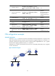
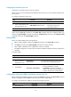
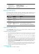
As shown in Figure 22, both Server and Host A send data to Host B through Router A. Suppose Server
sends critical packets and Host A sends non-critical packets. Congestion might occur on Serial 2/1/1
and result in packet loss because the rate of the incoming interface GigabitEthernet 1/0/1 is greater
than that of the outgoing interface Serial 2/1/1 on Router A.
Configure PQ, so that the critical packets from Server are transmitted preferentially when congestion
occurs in the network.
Figure 22 Network diagram
PPP
1.1.1.1/8
1.1.1.2/8
S2/1/1
GE1/0/1
GE1/0/1
S2/1/1
Host A
Host B
Router A
Router B
Server
Ethernet
2M
10M
Ethernet