HP HSR6800 Routers Interface Configuration Guide Part number: 5998-4488 Software version: HSR6800-CMW520-R3303P05 Document version: 6PW105-20140507
Legal and notice information © Copyright 2014 Hewlett-Packard Development Company, L.P. No part of this documentation may be reproduced or transmitted in any form or by any means without prior written consent of Hewlett-Packard Development Company, L.P. The information contained herein is subject to change without notice.
Contents Configuring Ethernet interfaces ··································································································································· 1 Overview············································································································································································ 1 Performing general configurations ························································································································
Configuring a CE1 interface in CE1 mode ········································································································ 28 Configuring other CE1 interface parameters ····································································································· 29 Configuring error packets diffusion restraint ······································································································ 30 Displaying and maintaining CE1 interfaces ······················
Overhead bytes ····················································································································································· 60 CPOS interface application scenario ·················································································································· 61 Configuring a CPOS interface ······································································································································ 61 Configuring an E1 chann
Configuring Ethernet interfaces All configuration tasks in this chapter are independent and optional. You can perform these configuration tasks in any order. Overview Ethernet is the most widespread wired LAN technology due to its flexibility, simplicity, and easy implementation. Your device supports the following types of Ethernet interfaces: • Layer 2 Ethernet interfaces—Physical Ethernet interfaces operating at the data link layer (Layer 2) to forward traffic within a subnet between hosts.
Use the display interface command to determine whether the fiber port or copper port of the combo interface is active. If the current port is the copper port, the output includes "Media type is twisted pair." If the current port is the fiber port, the output includes "Media type is optical fiber." You can use the display this command in combo interface view to determine whether the fiber port or copper port of the combo interface is active.
Step Command Remarks 1. Enter system view. system-view N/A 2. Enter 10-GE interface view. interface ten-gigabitethernet interface-number N/A 3. Configure the 10-GE interface to operate in LAN or WAN mode. port-mode { lan | wan } Configure the J0 or J1 byte when the 10-GE interface is operating in WAN mode. flag { j0 | j1 } sdh flag-value 4. Optional. By default, a 10-GE interface operates in LAN mode. Optional. By default, the value of the J0 and J1 bytes is 0.
Step Command Remarks Optional. 4. Set the duplex mode of the interface. duplex { auto | full | half } By default, the duplex mode is full for 10-GE interfaces, and is auto for other Ethernet interfaces. Fiber ports do not support the half keyword. Optional. 5. Set the port speed. speed { 10 | 100 | 1000 | auto } The default setting is auto. 6. Set the intended bandwidth for the interface. bandwidth bandwidth-value Optional. Fiber ports do not support the 10 or 100 keyword.
Step Enter system view. 1. Command Remarks system-view N/A • Enter Ethernet interface view: interface interface-type interface-number Enter Ethernet interface or subinterface view, or port group view. 2. • Enter port group view: port-group manual port-group-name • Enter Ethernet subinterface view: interface interface-type interface-number.subnumber Shut down the Ethernet interface or subinterface. 3. Use one of the commands.
Configuration restrictions and guidelines • On an interface that is physically down, you can only perform internal loopback testing. On an interface administratively shut down, you cannot perform internal or external loopback testing. • The speed, duplex, mdi, and shutdown commands are not available during loopback testing. • During loopback testing, the Ethernet interface operates in full duplex mode. When you disable loopback testing, the port returns to its duplex setting.
Step 2. Command Change the link mode of the specified Ethernet interfaces. port link-mode { bridge | route } interface-list To change the link mode of an Ethernet interface: Step Command 1. Enter system view. system-view 2. Enter Ethernet interface view. interface interface-type interface-number 3. Change the link mode of the Ethernet interface. port link-mode { bridge | route } Setting a statistics polling interval You can configure an interface statistics polling interval.
Step Command Remarks 2. Enter Ethernet interface view. interface interface-type interface-number N/A 3. Enable subinterface rate statistics collection on the Ethernet interface. sub-interface rate-statistic By default, subinterface rate statistics collection is disabled. Configuring a Layer 2 Ethernet interface The features in this section are supported on only SAP modules that are operating in bridge mode.
You create port groups manually. All settings made for a port group apply to all member ports of the group. For example, you can configure a traffic suppression threshold (see "Configuring storm suppression") for multiple interfaces in bulk by assigning these interfaces to a port group. Even though the settings are made on the port group, they are saved on each interface basis rather than on a port group basis.
To avoid congestion on GigabitEthernet 1/0/4, set 100 Mbps as the only option available for speed negotiation on port GigabitEthernet 1/0/1, GigabitEthernet 1/0/2, and GigabitEthernet 1/0/3. As a result, the transmission rate on each port connected to a server is limited to 100 Mbps. To set speed options for auto negotiation on an Ethernet interface: Step Command 1. Enter system view. system-view 2. Enter Ethernet interface view. interface interface-type interface-number 3.
Step Command Remarks Optional. Set the broadcast suppression threshold ratio. 3. broadcast-suppression { ratio | pps max-pps | kbps max-kbps } By default, broadcast traffic is allowed to pass through an interface. Optional. 4. Set the multicast suppression threshold ratio. multicast-suppression { ratio | pps max-pps | kbps max-kbps } 5. Set the unknown unicast suppression threshold ratio.
Enabling loopback detection on an Ethernet interface If a device receives a packet that it sent, a loop has occurred to the device. Loops might cause broadcast storms, which degrade network performance. You can use this feature to detect whether a loop has occurred. • Single-port loopback—Single-port loopback occurs when an interface receives a packet that it sent and the receiving interface is the same as the sending interface, as shown in 错误!未找到引用 源。.
Port type Actions No protective action is configured • Generate traps. • If loopback detection control is enabled, Hybrid or trunk port place the receiving interface in controlled mode. The interface discards all incoming packets, but still forwards outgoing packets. • Delete all MAC address entries of the A protective action is configured • Create traps and log messages. • If loopback detection control is enabled, take the configured protective action on the interface.
Step 7. 8. Command Enable loopback detection control on a trunk port or a hybrid port. Enable loopback detection in all VLANs on the trunk or hybrid port. Remarks Optional. loopback-detection control enable By default, loopback detection control is disabled. Optional. loopback-detection per-vlan enable By default, a trunk or hybrid port performs loopback detection only in its PVID. Optional. By default, when a loop is detected on an interface, the interface does not forward any data packet. 9.
When a crossover cable is used, set the interface to operate in the same MDI mode as its peer, or set either end to operate in auto mode. • To set the MDI mode of an Ethernet interface: Step Command Remarks 1. Enter system view. system-view N/A 2. Enter Ethernet interface view. interface interface-type interface-number N/A 3. Set the MDI mode of the Ethernet interface.
Shuts down automatically. The interface shuts down automatically and stops forwarding any traffic. When the blocked traffic is detected dropping below the lower threshold, the port does not forward the traffic. To bring up the interface, use the undo shutdown command or disable the storm control function. • Alternatively, you can configure the storm suppression function to control a specific type of traffic.
Configuring a Layer 3 Ethernet interface or subinterface Layer 3 Ethernet interface configuration task list Perform the following configuration on Ethernet interfaces operating in route mode: Task Remarks Optional. Setting the MTU for an Ethernet interface or subinterface Applicable to Layer 3 Ethernet interfaces and Ethernet subinterfaces. Optional. Configuring an Ethernet interface to operate in promiscuous mode Applicable to Layer 3 Ethernet interfaces.
Step Command Remarks 2. Enter Ethernet interface view. interface interface-type interface-number N/A 3. Configure the Ethernet interface to operate in promiscuous mode. promiscuous By default, an Ethernet interface does not operate in promiscuous mode. Enabling fast forwarding on an Ethernet interface IMPORTANT: Enabling or disabling fast forwarding on an Ethernet interface of a SAP module restores all configurations of the interface to the default.
Task Command Remarks display interface [ interface-type ] brief [ down ] [ | { begin | exclude | include } regular-expression ] Display Ethernet interface or subinterface information. display interface interface-type { interface-number | interface-number.subnumber } [ brief [ description ] ] [ | { begin | exclude | include } regular-expression ] Available in any view. Display traffic statistics for the specified interfaces.
Ten-GigabitEthernet 1/0/0 and Ten-GigabitEthernet 2/0/0 of Router B are on different SAP-4EXP modules. • Configure fast forwarding on Router B to improve packet forwarding efficiency. Figure 4 Network diagram XGE1/0/0 11.1.1.1/8 XGE2/0/0 22.1.1.1/8 XGE1/0/0 11.1.1.2/8 RouterA RouterB XGE1/0/0 22.1.1.2/8 RouterC Configuration procedure 1. Configure Router A: # Configure an IP address for the interface Ten-GigabitEthernet 1/0/0.
Verifying the configuration # Ping Ten-GigabitEthernet 1/0/0 of Router C from Router A. [RouterA] ping 22.1.1.2 PING 22.1.1.2: 56 data bytes, press CTRL_C to break Reply from 22.1.1.2: bytes=56 Sequence=1 ttl=254 time=2 ms Reply from 22.1.1.2: bytes=56 Sequence=2 ttl=254 time=1 ms Reply from 22.1.1.2: bytes=56 Sequence=3 ttl=254 time=1 ms Reply from 22.1.1.2: bytes=56 Sequence=4 ttl=254 time=2 ms Reply from 22.1.1.2: bytes=56 Sequence=5 ttl=254 time=2 ms --- 22.1.1.
Configuring ATM interfaces ATM interface ATM Asynchronous Transfer Mode (ATM) is a backbone network technology for transmission of audio, video, and data. By virtue of its flexibility and support for multimedia services, ATM is regarded as a core technology for implementing broadband communications. The ATM physical layer lies at the bottom of the ATM reference model. Though it involves specific transmission media, its functionality does not rely on the transmission mechanism and speed of a specific medium.
Configuring an ATM OC-3c/STM-1 interface Overview This section covers only the physical configurations of the interface. For more information about how to configure ATM (including PVCs), see Layer 2—WAN Configuration Guide. Configuration procedure To configure an ATM OC-3c/STM-1 interface: Step Command Remarks 1. Enter system view. system-view N/A 2. Enter ATM OC-3c/STM-1 interface view. interface atm interface-number N/A 3. Set the clock mode. clock { master | slave } 4.
Task Display information about a specified or all ATM interfaces. Command display interface [ atm ] [ brief [ down ] ] [ | { begin | exclude | include } regular-expression ] display interface atm interface-number [ brief [ description ] ] [ | { begin | exclude | include } regular-expression ] Remarks Available in any view. Clear the statistics on all PVCs on a specified ATM interface. reset atm interface [ atm [ interface-number ] ] Available in user view. Clear the statistics on an ATM interface.
Configuring WAN interfaces In terms of link type, wide area networks (WANs) include Frame Relay (FR) and ATM. Routers are designed with the synchronous serial interface, ATM interface, and CE1 interface. The system supports the synchronous serial interface, CE1 interface, CT1 interface, CE3 interface, and CT3 interface. Configuring a synchronous serial interface A synchronous serial interface has the following features: • Operates in either DTE or DCE mode.
Step Command Remarks • On DTE side: 7. Set the clock selection mode. clock { dteclk1 | dteclk2 | dteclk3 | dteclk4 | dteclkauto } • On DCE side: clock { dceclk1 | dceclk2 | dceclk3 } 8. 9. Set transmit-clock or receive-clock signal inversion on the DTE side. invert { transmit-clock | receive-clock } Set the MTU. mtu size Optional. The default is dceclk1 for DCE side and dteclk1 for DTE side. Optional. Disabled by default. Optional. The default is 1500 bytes. 10. Set the CRC mode.
Enabling subinterface rate statistics collection on a serial interface CAUTION: Use this function with caution, because it is system resource demanding. After enabling subinterface rate statistics collection on a serial interface, the device periodically refreshes the rate statistics for the subinterfaces of the serial interface. You can use the display interface command to view the rate statistics.
1. A CE1 interface in E1 mode provides 2.048 Mbps data bandwidth and cannot be divided into timeslots. It has the same logical features as the synchronous serial interface. It supports link layer protocols such as PPP and FR and the network protocol IP. 2. A CE1 interface in CE1 mode is physically divided into 32 timeslots numbered 0 to 31. Timeslot 0 is used to transmit synchronizing information.
For each channel set, the system automatically creates a serial interface named serial interface-number:set-number. These interfaces are logically equivalent to synchronous serial interfaces where you can make other configurations such as: • Data link protocol such as PPP and FR • IP addressing Configuring other CE1 interface parameters Step Command Remarks 1. Enter system view. system-view N/A 2. Enter CE1 interface view. controller e1 number N/A 3. Configure the interface description.
Step Command 15. Enable user data inversion. data-coding { inverted | normal } 16. Set the intended bandwidth for the CE1 interface. bandwidth bandwidth-value 17. Shut down the CE1 interface. shutdown 18. Enter the view of the synchronous serial interface created on the CE1 interface. interface serial interface-number:set-number 19. Set the CRC mode. crc { 16 | 32 | none } Remarks Optional. Disabled by default. Optional. Optional. Up by default. N/A Optional. By default, 16-bit CRC is adopted.
Task Command Remarks Clear the controller counter for a CE1 interface. reset counters controller e1 interface-number Available in user view. Configuring a CT1 interface A CT1 interface can operate only in channelized mode. When it is working as a CT1 interface, all the timeslots (numbered 1 to 24) can be randomly divided into groups. Each of these groups can form one channel set for which the system automatically creates an interface logically equivalent to a synchronous serial interface.
Step 5. Set the cable length and attenuation. Command Remarks cable long { 0db | -7.5db | -15db | -22.5db } Optional. cable short { 133ft | 266ft | 399ft | 533ft | 655ft } 6. Set the line code format. code { ami | b8zs } 7. Set the clock mode. clock { master | slave } 8. Set the framing format. frame-format { sf | esf } The long 0db keyword applies by default. Optional. The default is B8ZS1. Optional. The default is slave, which is line clock. Optional. The default is ESF. Optional. 9.
Step Command Remarks 17. Send remote loopback control code. sendloopcode { fdl-ansi-llb-down | fdl-ansi-llb-up | fdl-ansi-plb-down | fdl-ansi-plb-up | fdl-att-plb-down | fdl-att-plb-up | inband-llb-down | inband-llb-up } 18. Set the intended bandwidth for the CT1 interface. bandwidth bandwidth-value 19. Shut down the CT1/PRI interface. shutdown 20. Return to system view quit N/A 21. Enter the view of the synchronous serial interface created on the CT1 interface.
If the packet error rate for the detection period exceeds the PER threshold, the interface automatically shuts down to avoid the risk of error packets diffusion. At the same time, the renew timer starts. When the timer expires, the interface automatically comes up. To configure error packets diffusion restraint: Step Command Remarks 1. Enter system view. system-view N/A 2. Enable error packets diffusion restraint. error-diffusion restraint enable N/A Optional. 3.
Configuring an E1-F interface in framed mode Step Command Remarks 1. Enter system view. system-view N/A 2. Enter E1-F interface view. interface serial interface-number N/A 3. Configure the interface to operate in framed mode. undo fe1 unframed 4. Bundle timeslots on the interface. fe1 timeslot-list list 5. Enable RAI detection on the interface. fe1 alarm detect rai Set other interface parameters. See "Configuring other E1-F interface parameters." 6. Optional.
Step Command Remarks Optional. 5. Set the clock mode. fe1 clock { master | slave } 6. Enable automatic clock mode change. clock-change auto 7. Set the cable type. fe1 cable { long | short } 8. Configure the CRC mode. crc { 16 | 32 | none } 9. Enable AIS test. fe1 detect-ais The default is slave, which is line clock. Optional. Disabled by default. Optional. The long keyword applies by default. Optional. 16-bit CRC by default. Optional. By default, AIS test is performed. Optional. 10.
Step Command Remarks 1. Enter system view. system-view N/A 2. Enable error packets diffusion restraint. error-diffusion restraint enable N/A Optional. 3. Configure error packets diffusion restraint parameters. error-diffusion restraint config detect-timer renew-timer threshold By default, the detect-timer is 30 seconds, the renew-timer is 600 seconds, and the PER threshold is 20%.
Step Command Remarks Optional. 3. Configure the interface description. description text By default, the description of an interface is interface-name Interface. If no timeslot range is specified, all timeslots are bundled into one channel set. Bundle timeslots on the interface into a channel set. ft1 timeslot-list list [ speed { 56k | 64k } ] 5. Set the cable length and attenuation. ft1 cable { long decibel | short length } 6. Set the line code format. ft1 code { ami | b8zs } 7.
Step Command 14. Set the type of line idle code. ft1 idlecode { 7e | ff } 15. Set the type of interframe filling tag. ft1 itf type { 7e | ff } 16. Set the number of interframe filling tags. ft1 itf number number 17. Enable loopback and set the loopback mode. ft1 loopback { local | remote | payload } 18. Send remote control loopback code.
If the packet error rate for the detection period exceeds the PER threshold, the interface automatically shuts down to avoid the risk of error packets diffusion. At the same time, the renew timer starts. When the timer expires, the interface automatically comes up. To configure error packets diffusion restraint: Step Command Remarks 1. Enter system view. system-view N/A 2. Enable error packets diffusion restraint. error-diffusion restraint enable N/A Optional.
When the E1 line is working in framed (CE1) mode, you can bundle timeslots on it. The system automatically creates a serial interface named serial number/line-number:set-number for it. This interface operates at N × 64 kbps and is logically equivalent to a synchronous serial interface where you can make other configurations. CE3 interfaces support link layer protocols PPP, HDLC, and FR and network protocol IP. Configuring a CE3 interface in E3 mode Step Command Remarks 1. Enter system view.
Step 5. Set other interface parameters. Command Remarks See "Configuring other CE3 interface parameters." Optional. Configure PPP, FR, and IP address for the CE3 interface if the network requires. Configuring other CE3 interface parameters Step Command Remarks 1. Enter system view. system-view N/A 2. Enter CE3 interface view. controller e3 interface-number N/A 3. Configure the interface description. description text 4.
Step Command Remarks 11. Enter synchronous serial interface view of an interface formed by a CE3 interface. • interface serial number/line-number:0 • interface serial N/A number/line-number:set-number Optional. 12. Set the CRC mode crc { 16 | 32 | none } By default, 16-bit CRC is adopted. Displaying and maintaining CE3 interfaces Task Command Remarks Display the state information of a CE3 interface.
Configuring a CT3 interface Both T3 and T1 belong to the T-carrier system promoted by ANSI. T3 uses the digital signal level DS-3 and operates at 44.736 Mbps. CT3 interfaces support two operating modes: T3 (unchannelized) and CT3 (channelized). • In T3 mode, a CT3 interface is a synchronous serial interface with 44.736 Mbps of data bandwidth, on which no timeslots are divided. • In CT3 mode, a CT3 interface can be demultiplexed into 28 channels of T1 signals.
Step 3. Command Configure the interface to operate in CT3 mode. Remarks Optional. using ct3 The default operating mode is CT3 mode. • Set the operating mode to unframed (T1) mode: t1 line-number unframed • Set the operating mode to 4. Set the operating mode of a T1 line on the CT3 interface to unframed mode or framed mode. framed (CT1) mode and bundle timeslots on the CT1 interface: a.
Step Command Remarks Optional. 6. Set the cable length. cable feet The default is 14.9 meters (49 feet). Optional. 7. Set the physical state change suppression interval. link-delay delay-time By default, physical state change suppression is disabled on the interface. • On the CT3 interface: loopback { local | payload | remote } 8. Set the loopback mode. • On a T1 line: t1 line-number set loopback.{ local | payload | remote } • On the CT3 interface: frame-format { c-bit | m23 } 9.
Step Command Remarks 14. Place a T1 line on the far-end CT3 interface in a loopback. t1 line-number sendloopcode { fdl-ansi-line-up | fdl-ansi-payload-up | fdl-att-payload-up | inband-line-up } Optional. Optional. By default, FDL is disabled. 15. Set the FDL format for a T1 channel. t1 line-number set fdl { ansi | att | both | none } This operation applies only to T1 channels that are formed on CT3 interfaces, operate in channelized mode, and use ESF as the T1 framing format. 16.
Task Command Remarks Available in CT3 interface view. CAUTION: Shut down a CT3 interface. shutdown Bring up a CT3 interface. undo shutdown Make sure you are fully aware of the impact of the shutdown action on your network. Available in CT3 interface view. Available in CT3 interface view. Shut down a T1 line. t1 line-number shutdown Bring up a T1 line. undo t1 line-number shutdown CAUTION: Make sure you are fully aware of the impact of the shutdown action on your network.
Configuring POS interfaces Overview SONET Synchronous Optical Network (SONET), a synchronous transmission system defined by the ANSI, is an international standard transmission protocol. It adopts optical transmission. SDH Synchronous Digital Hierarchy (SDH), defined by the CCITT (today’s ITU-T), uses a SONET rate subset. SDH adopts synchronous multiplexing and allows for flexible mapping structure.
Step Command Remarks Optional. 3. Set the interface description. description text 4. Set the clock mode. clock { master | slave } 5. Set the CRC length. crc { 16 | 32 } 6. Set the loopback mode. loopback { local | remote } By default, the description of a POS interface is interface name Interface, for example, POS1/2/0 Interface. Optional. The default is slave. Optional. The default is 32 bits. Optional. Loopback is disabled by default. Optional. By default: • The C2 overhead byte is 7.
Step Command Remarks Optional. 13. Set the signal degrade (SD) or signal fail (SF) alarm threshold for the interface. By default, the SD alarm threshold is 10e-6 (the value argument is 6), and the SF alarm threshold is 10e-3 (the value argument is 3). threshold { sd | sf } value Optional. 14. Set the physical state change suppression interval on the interface. link-delay seconds By default, physical state change suppression is disabled on the interface. 15.
Changing the interface type You can change the interface type between POS and GE for interfaces on the HIM-TS8P interface module. To change the type of an interface: Step 1. Enter system view. Command Remarks system-view N/A • Enter POS interface view: interface pos interface-number 2. Enter interface view. • Enter Layer 3 GigabitEthernet To change a POS interface to an Ethernet interface, enter POS interface view. To change an Ethernet interface to a POS interface, enter Ethernet interface view.
POS interface configuration example Directly connecting routers through POS interfaces Network requirements As shown in Figure 5, use a pair of single mode optic fibers (for receiving and sending data, respectively) to connect the POS interfaces on Router A and Router B. Encapsulate the interfaces with PPP. Figure 5 Network diagram Configuration procedure 1. Configure Router A: # Configure interface POS 2/1/0, setting its physical parameters to defaults.
Connecting routers through POS interfaces across frame relay Network requirements As shown in Figure 6, connect routers to a public frame relay network through POS interfaces. The routers are premise equipment that work as DTE side of frame relay. Router A uses frame relay sub-interfaces to connect Router B and Router C in different network segments. Figure 6 Network diagram Configuration procedure 1. Configure Router A: # Configure POS interface 2/1/0.
# Configure frame relay encapsulation on the interface. [RouterB-Pos2/1/0] link-protocol fr [RouterB-Pos2/1/0] fr interface-type dte [RouterB-Pos2/1/0] ip address 10.10.10.2 255.255.255.0 [RouterB-Pos2/1/0] fr dlci 70 [RouterB-Pos2/1/0] fr map ip 10.10.10.1 70 [RouterB-Pos2/1/0] mtu 1500 3. Configure Router C in the same way Router B is configured. Verifying the configuration Check interface connectivity with the display interface pos command and test network connectivity with the ping command.
Configuring CPOS interfaces Overview SONET/SDH Synchronous Optical Network (SONET), a synchronous transmission system defined by the American National Standards Institute (ANSI), is an international standard transmission protocol. It adopts optical transmission. Synchronous Digital Hierarchy (SDH) is defined by the Consultative Committee for International Telegraph and Telephone (CCITT), today’s Telecommunication Standardization Sector of the International Telecommunication Union (ITU-T).
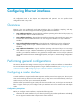
Figure 7 STM-N frame structure STM-N is a rectangle-block frame structure of 9 rows x 270 x N columns, where the N in STM-N equals the N columns. N takes the value 1, 4, 16, and so on, indicating the number of STM-1 signals that form SDH signal. The STM-N frame structure consists of three parts: the section overhead (SOH), which includes the regenerator section overhead (RSOH) and the multiplex section overhead (MSOH); the administration unit pointer (AU-PTR); and payload.
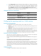
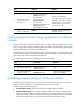
Figure 8 Process of multiplexing E1 channels to form STM-1 Figure 9 Process of multiplexing T1 channels to form STM-1 STM-1 ×1 AUG-1 ×1 AU-4 VC-4 Mapping TUG-3 ×7 ×3 AU-3 ×3 VC-3 ×7 TUG-2 ×4 C-11 TU-11 VC-11 Aligning Multiplexing C-11: 1.
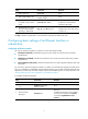
Figure 11 Process of multiplexing T3 channels to form STM-1 In actual applications, different countries and regions might adopt different multiplexing structures. To ensure interoperability, the multiplex mode command is provided on CPOS interfaces. This allows you to select the AU-3 or AU-4 multiplexing structure. Calculating E1/T1/E3/T3 channel sequence numbers Since CPOS interfaces adopt the byte interleaved multiplexing mode, the lower-order VCs are not arranged in order in a higher-order VC.
You can calculate TU-12 numbers in the same way when the AU-3 path is used. When 63 E1 channels or 84 T1 channels are configured on a CPOS interface, you can reference E1 or T1 channels by referencing the numbers in the range of 1 to 63 or 1 to 84. When connecting your device to channelized STM-1 interfaces on devices of other vendors, you should consider the possible numbering differences due to different channel referencing methods.
Similar to the J0 byte, the higher-order VC-N path trace byte J1 is included in the higher-order path overhead to repeatedly send the higher-order path access point identifier, based on which the receiving end of the path can make sure it is in continuous connection with the specified sender. The sender and the recipient must use the same J1 byte.
To configure a CPOS interface: Step Command Remarks 1. Enter system view. system-view N/A 2. Enter CPOS interface view. controller cpos cpos-number N/A Optional. 3. Set the interface description. description text 4. Set the framing format. frame-format { sdh | sonet } 5. Set the clock mode. clock { master | slave } 6. Set the loopback mode. loopback { local | remote } 7. Configure the AUG multiplexing mode. 8. 9.
Configuring an E1 channel Step Command Remarks 1. Enter system view. system-view N/A 2. Enter CPOS interface view. controller cpos cpos-number N/A 3. Set the framing format for E1. e1 e1-number set frame-format { crc4 | no-crc4 } Optional. 4. Set the clock mode for E1. e1 e1-number set clock { master | slave } Optional. 5. Set the loopback mode for E1. e1 e1-number set loopback { local | payload | remote } Optional. e1 e1-number set flag c2 c2-value 6. Set the overhead bytes for E1.
Configuring a T1 channel Step Command Remarks 1. Enter system view. system-view N/A 2. Enter CPOS interface view. controller cpos cpos-number N/A 3. Set the framing format for T1. t1 t1-number set frame-format { esf | sf } Optional. 4. Set the clock mode for T1. t1 t1-number set clock { master | slave } Optional. 5. Set the loopback mode for T1. t1 t1-number set loopback { local | payload | remote } Optional. t1 t1-number set flag c2 c2-value 6. Set the overhead bytes for T1.
Configuring an E3 channel Step Command Remarks 1. Enter system view. system-view N/A 2. Enter CPOS interface view. controller cpos cpos-number N/A 3. Create a serial interface corresponding to the unframed E3 channel. using e3 e3-number 4. Configure overhead bytes for VC-3 frames. flag vc-3 path-number { c2 c2-value | j1 { sdh sdh-string | sonet sonet-string } | s1s0 s1s0-value } Optional. 5. Configure overhead bytes for VC-4 frames.
Step Command Remarks Optional. 4. Enable alarm signal detection and generation on the T3 channel. t3 t3-number set alarm { detect | generate { ais | febe | idle | rai } } By default, alarm signal detection and generation are disabled on T3 channels. 5. Enable a bit error rate test (BERT) of the specified pattern on the T3 channel. t3 t3-number set bert pattern { 2^7 | 2^11 | 2^15 | qrss } time time-number Optional. Configure the clock mode of the T3 channel.
Displaying and maintaining CPOS interfaces Task Command Remarks Display information about channels on a specified or all CPOS interfaces. display controller cpos [ cpos-number ] [ | { begin | exclude | include } regular-expression ] Available in any view. Display information about a specified E1 channel on a CPOS interface. display controller cpos cpos-number e1 e1-number [ | { begin | exclude | include } regular-expression ] Available in any view.
Figure 15 Network diagram Configuration procedure Because the clock source of a SONET/SDH network is more precise than the internal clock source of the device, when connecting the device to a SONET/SDH device, configure the clock mode of the SONET/SDH device as master. 1. Configure Router A: # Configure the E1 channels of CPOS interface CPOS 2/0 to operate in unframed mode.
# Configure Serial 2/0/1:0 and Serial2/0/2:0 and assign them to MP-group 1.
[RouterA] interface serial2/0/0/2:0 [RouterA-Serial2/0/0/2:0] ip address 12.1.1.2 24 [RouterA-Serial2/0/0/2:0] quit 2. Configure Router B: # Create the serial interface corresponding to the E3 interface. system-view [RouterB] controller e3 2/0/1 [RouterB-E3 2/0/1] using e3 [RouterB-E3 2/0/1] quit # Configure interface Serial 2/0/1/0:0. [RouterB] interface serial2/0/1/0:0 [RouterB-Serial2/0/1/0:0] ip address 11.1.1.
71
Configuring E-CPOS interfaces Overview SONET Synchronous Optical Network (SONET), a synchronous transmission system defined by the ANSI, is an international standard transmission protocol over fiber-optic. SONET transmission rates form a sequence of OC-1 (51.84 Mbps), OC-3 (155 Mbps), OC-12 (622 Mbps), and OC-48 (2.5 Gbps). Because signals are synchronous, SONET can multiplex signals conveniently. SDH Synchronous Digital Hierarchy (SDH), defined by the CCITT (today’s ITU-T) uses a SONET rate subset.
Multiplexing STM frames An STM-1 frame adopts the rectangular structure of 270 columns and 9 rows, with the first 10 columns as the overhead and the rest 260 columns as the payload. An STM-N frame is formed by interleaving N STM-1 frames. Figure 18 STM-1 frame structure • SOH—The SDH section overhead. It is used for monitoring the entire STM-1 frame and does not carry user data. The SOH consists of the regenerator section overhead (RSOH) and the multiplex section overhead (MSOH).
Figure 19 Process of multiplexing four STM-1 frames into an STM-4 frame The recipient will demultiplex a received STM-4 frame into four STM-1 frames. During the multiplexing process, the A1, A2, J0, Z0, B1, E1, F1, D1, D2, and D3 fields in the RSOH of the first frame are multiplexed into the STM-4 frame while those of the rest three frames are treated as invalid. The other fields of each frame are multiplexed into the STM-4 frame separately.
SONET SDH Rate STS-12 STM-4 622.080 Mbps STS-48 STM-16 2488.320 Mbps Overhead bytes SDH provides hierarchical monitoring and management functions. It provides section level monitoring and path level monitoring. Section level monitoring is subdivided into regenerator section level monitoring and multiplex section level monitoring, while the path level monitoring is subdivided into higher-order path level monitoring and lower-order path level monitoring.
• Tributary unit (TU) and tributary unit group (TUG)—TU is the information structure that provides adaptation between higher-order paths and lower-order paths. TUG is a set of one or more TUs whose locations are fixed in higher-order VC payload. • Administrative unit (AU) and administrative unit group (AUG)—AU is the information structure that provides adaptation between the higher-order path layer and the multiplex section layer.
Figure 21 Network diagram for an E-CPOS application In actual applications, the connection between these low-end routers and the E-POS interfaces might span more than one transmission network and as such, might require relay. This is similar to the scenario where low-end devices are connected to Router A through one or multiple E3/T3 leased lines.
Step Command Remarks Optional. 3. Set the interface description. description text 4. Set the framing format. frame-format { sdh | sonet } 5. Configure the clocking mode. clock { master | slave } 6. Configure the loopback mode. loopback { local | remote } 7. Configure the J0 byte. flag j0 { sdh j0-string | sonet j0-value } 8. Configure the signal degrade (SD) alarm threshold and signal fail (SF) alarm threshold.
Follow these guidelines when you configure the operating mode of an E-CPOS interface/channel: • oc-48 and oc-48c correspond to 2.5 Gbps E-CPOS interfaces. • oc-12 and oc-12c correspond to 622 Mbps E-CPOS interfaces or 622 Mbps channels channelized from 2.5 Gbps E-CPOS interfaces. • oc-3 and oc-3c correspond to 155 Mbps E-CPOS interfaces or 155 Mbps channels channelized from 2.5 Gbps E-CPOS interfaces or 622 Mbps E-CPOS interfaces. Configuring the interface/channel operating mode on a 2.
Step Command Remarks Optional. By default, a 622 Mbps E-CPOS interface operates in channelized mode. Configure the 622 Mbps E-CPOS interface to operate in channelized mode. using oc-12 5. Create a 155 Mbps channel and enter its view. oc-3 oc-3-number N/A 6. Configure the 155 Mbps channel to operate in concatenated mode using oc-3c The default is the channelized mode. 4. Before creating a 155 Mbps POS channel, you must configure the 2.5 Gbps E-CPOS interface to operate in channelized mode.
Configuring the operating mode for a 155 Mbps E-CPOS interface You can use the using command to configure a 155 Mbps E-CPOS interface to operate in channelized mode or concatenated mode. To create POS channels, configure the concatenated mode. On a 155 Mbps E-CPOS interface in concatenated mode, you can create one 155 Mbps POS interface. To configure the operating mode of a 155 Mbps E-CPOS interface: Step Command Remarks 1. Enter system view. system-view N/A 2. Enter E-CPOS interface view.
• Each interface uses PPP on the data link layer. All routers use the clock of the SDH transmission device. The MTU of each interface is 9200 bytes. Figure 22 Network diagram Configuration procedure 1. Configure Router A: # Configure the clock mode of interface E-CPOS 2/0/0. system-view [RouterA] controller e-cpos 2/0/0 [RouterA-E-Cpos2/0/0] clock master # Create two 155 Mbps POS interfaces on interface E-CPOS 2/0/0.
[RouterB-E-Cpos2/0/0-oc-3-1] using oc-3c [RouterB-E-Cpos2/0/0-oc-3-1] quit [RouterB-E-Cpos2/0/0] oc-3 2 [RouterB-E-Cpos2/0/0-oc-3-2] using oc-3c [RouterB-E-Cpos2/0/0-oc-3-2] quit [RouterB-E-Cpos2/0/0] quit # Configure channelized interface POS 2/0/0/1:0. [RouterB] interface pos2/0/0/1:0 [RouterB-pos2/0/0/1:0] ip address 10.110.4.2 255.255.255.0 [RouterB-pos2/0/0/1:0] mtu 9200 [RouterB-pos2/0/0/1:0] quit # Configure channelized interface POS 2/0/0/2:0.
Figure 23 Network diagram Configuration procedure 1. Configure Router A: # Configure the clock mode of interface E-CPOS 2/0/0. system-view [RouterA] controller e-cpos 2/0/0 [RouterA-E-Cpos2/0/0] clock master # Create two 155 Mbps POS interfaces on interface E-CPOS 2/0/0. [RouterA-E-Cpos2/0/0] oc-12 4 [RouterA-E-Cpos2/0/0-oc-12-4] oc-3 4 [RouterA-E-Cpos2/0/0-oc-12-4-oc-3-4] using oc-3c # Configure channelized interface POS 2/0/0/4/4:0.
• POS interfaces channelized from the local E-CPOS interface are not the same as POS interfaces channelized from the remote E-CPOS interface in POS interface number. • PPP authentication fails on the virtual POS interface. PPP authentication might fail due to incorrect PPP authentication parameters. You can use the display interface pos interface-number command to display the multiplexing path and PPP link negotiation information of the specified POS interface.
86
Configuring loopback and null interfaces Configuring a loopback interface Introduction A loopback interface is a virtual interface. The physical layer state and link layer protocols of a loopback interface are always up unless the loopback interface is manually shut down. A loopback interface is widely used in the following scenarios: • A loopback interface address can be configured as the source address of the IP packets that the device generates.
You can configure settings such as IP addresses and IP routes on loopback interfaces. For more information, see Layer 3—IP Services Configuration Guide and Layer 3—IP Routing Configuration Guide. Configuring a null interface Introduction A null interface is a completely software-based logical interface, and is always up. However, you cannot use it to forward data packets or configure an IP address or link layer protocol on it.
Task Display information about loopback interfaces. Display information about the null interface.
Support and other resources Contacting HP For worldwide technical support information, see the HP support website: http://www.hp.
Conventions This section describes the conventions used in this documentation set. Command conventions Convention Description Boldface Bold text represents commands and keywords that you enter literally as shown. Italic Italic text represents arguments that you replace with actual values. [] Square brackets enclose syntax choices (keywords or arguments) that are optional. { x | y | ... } Braces enclose a set of required syntax choices separated by vertical bars, from which you select one.
Network topology icons Represents a generic network device, such as a router, switch, or firewall. Represents a routing-capable device, such as a router or Layer 3 switch. Represents a generic switch, such as a Layer 2 or Layer 3 switch, or a router that supports Layer 2 forwarding and other Layer 2 features. Represents an access controller, a unified wired-WLAN module, or the switching engine on a unified wired-WLAN switch. Represents an access point.
Index ACDEOPRT Displaying and maintaining an Ethernet interface or subinterface,18 A ATM interface,22 Displaying and maintaining ATM interfaces,23 C Displaying and maintaining CPOS interfaces,67 Changing the interface type,52 Displaying and maintaining E-CPOS interfaces,81 Displaying and maintaining loopback and null interfaces,88 Configuring a CE1 interface,27 Configuring a CE3 interface,40 Displaying and maintaining POS interfaces,52 Configuring a CPOS interface,61 Configuring a CT1 interface,31