
R3303-HP HSR6800 Routers Interface Configuration Guide

53
POS interface configuration example
Directly connecting routers through POS interfaces
Network requirements
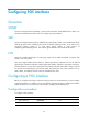
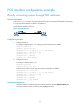
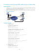
As shown in Figure 5, use a pair of single mode optic fibers (for receiving and sending data, respectively)
to connect the POS interfaces on Router A and Router B.
Encapsulate the interfaces with PPP.
Figure 5 Network diagram
Configuration procedure
1. Configure Router A:
# Configure interface POS 2/1/0, setting its physical parameters to defaults.
<RouterA> system-view
[RouterA] interface pos 2/1/0
[RouterA-Pos2/1/0] ip address 10.110.1.10 255.255.255.0
[RouterA-Pos2/1/0] link-protocol ppp
[RouterA-Pos2/1/0] mtu 1500
[RouterA-Pos2/1/0] shutdown
[RouterA-Pos1/0] undo shutdown
2. Configure Router B:
# Configure interface POS 2/1/0.
<RouterB> system-view
[RouterB] interface pos 2/1/0
# Set the clock mode to master and other physical parameters to defaults.
[RouterB-Pos2/1/0] clock master
[RouterB-Pos2/1/0] ip address 10.110.1.11 255.255.255.0
[RouterB-Pos2/1/0] link-protocol ppp
[RouterB-Pos2/1/0] mtu 1500
[RouterB-Pos2/1/0] shutdown
[RouterB-Pos2/1/0] undo shutdown
Verifying the configuration
Check the interface connectivity between the POS interfaces with the display interface pos
command and test network connectivity with the ping command.