
R3303-HP HSR6800 Routers Interface Configuration Guide

54
Connecting routers through POS interfaces across frame relay
Network requirements
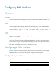
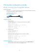
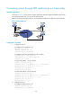
As shown in Figure 6, connect routers to a public frame relay network through POS interfaces. The routers
are premise equipment that work as DTE side of frame relay.
Router A uses frame relay sub-interfaces to connect Router B and Router C in different network segments.
Figure 6 Network diagram
Configuration procedure
1. Configure Router A:
# Configure POS interface 2/1/0.
<RouterA> system-view
[RouterA] interface pos 2/1/0
[RouterA-Pos2/1/0] clock slave
# Configure frame relay encapsulation on the interface.
[RouterA-Pos2/1/0] link-protocol fr
[RouterA-Pos2/1/0] fr interface-type dte
[RouterA-Pos2/1/0] quit
# Create sub-interface 1 on the interface.
[RouterA] interface pos 2/1/0.1
[RouterA-Pos2/1/0.1] ip address 10.10.10.1 255.255.255.0
[RouterA-Pos2/1/0.1] fr map ip 10.10.10.2 50
[RouterA-Pos2/1/0.1] mtu 1500
[RouterA-Pos2/1/0.1] quit
# Create sub-interface 2 on the interface.
[RouterA] interface pos 2/1/0.2
[RouterA-Pos2/1/0.2] ip address 20.10.10.1 255.255.255.0
[RouterA-Pos2/1/0.2] fr map ip 20.10.10.2 60
[RouterA-Pos2/1/0.2] mtu 1500
[RouterA-Pos2/1/0.2] quit
2. Configure Router B:
# Configure interface POS 2/1/0.
[RouterB] interface pos 2/1/0
[RouterB-Pos2/1/0] clock slave