
R3303-HP HSR6800 Routers Interface Configuration Guide

84
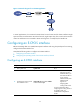
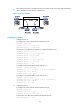
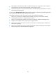
Figure 23 Network diagram
Configuration procedure
1. Configure Router A:
# Configure the clock mode of interface E-CPOS 2/0/0.
<RouterA> system-view
[RouterA] controller e-cpos 2/0/0
[RouterA-E-Cpos2/0/0] clock master
# Create two 155 Mbps POS interfaces on interface E-CPOS 2/0/0.
[RouterA-E-Cpos2/0/0] oc-12 4
[RouterA-E-Cpos2/0/0-oc-12-4] oc-3 4
[RouterA-E-Cpos2/0/0-oc-12-4-oc-3-4] using oc-3c
# Configure channelized interface POS 2/0/0/4/4:0.
[RouterA-E-Cpos2/0/0-oc-12-4-oc-3-4] interface pos2/0/0/4/4:0
[RouterA-pos2/0/0/4/4:0] ip address 10.110.4.1 255.255.255.0
2. Configure Router B:
# Create two 155 Mbps POS interfaces on interface E-CPOS 2/0/0.
<RouterB> system-view
[RouterB] controller e-cpos 2/0/0
[RouterB-E-Cpos2/0/0] oc-12 4
[RouterB-E-Cpos2/0/0-oc-12-4] oc-3 4
[RouterB-E-Cpos2/0/0-oc-12-4-oc-3-4] using oc-3c
# Configure channelized interface POS 2/0/0/4/4:0.
[RouterB-E-Cpos2/0/0-oc-12-4-oc-3-4] interface pos2/0/0/4/4:0
[RouterB-pos2/0/0/4/4:0] ip address 10.110.4.2 255.255.255.0
After the connection is established, Router A can successfully ping Router B.
Troubleshooting E-CPOS interfaces
Symptom
An E-CPOS interface is physically up, the channelized POS interfaces on it are up, but its link layer is
down.
Solution
• The physical parameter settings (such as clock source and scrambling) on the E-CPOS interface do
not match those on the remote E-CPOS interface.
• The link layer protocol of the POS channel does match that of the remote POS channel.
• The bandwidth of POS interfaces channelized from the local E-CPOS interface is not the same as
that of POS interfaces channelized from the remote E-CPOS interface.