
R3303-HP HSR6800 Routers IP Multicast Configuration Guide

189
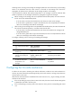
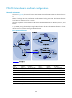
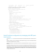
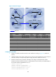
Figure 55 Network diagram
Device Interface IP address
Device
Interface
IP address
Source 1 - 192.168.1.100/24 Router D GE2/1/1 10.110.5.1/24
Source 2 - 192.168.3.100
/
24
POS5/1/0 10.110.3.2
/
24
Router
A
GE2/1/1 10.110.1.1
/
24
Loop0
2.2.2.2
/
32
GE2/1/2 10.110.2.1/24 Router E GE2/1/1 10.110.5.2/24
Loop0 1.1.1.1/32
GE2/1/2 192.168.3.1/24
Router B GE2/1/1 10.110.1.2
/
24
Router F
GE2/1/1 10.110.6.1/24
GE2/1/2 192.168.1.1/24 S3/1/0 10.110.4.2/24
POS5/1/0 10.110.3.1
/
24
Router G
GE2/1/1 10.110.6.2/24
Router C GE2/1/1 10.110.2.2
/
24
GE2/1/2 192.168.4.1/24
GE2/1/2 192.168.2.1/24 Loop0 3.3.3.3/32
S3/1/0 10.110.4.1
/
24
Configuration procedure
1. Assign an IP address and subnet mask to each interface according to Figure 55. (Details not
shown.)
2. Configure OSPF on the routers to make sure the routers are interoperable at the network layer in
each AS, and they can dynamically update routing information. (Details not shown.)
3. Enable IP multicast routing, PIM-SM, and IGMP, and configure a PIM-SM domain border:
# Enable IP multicast routing on Router C, enable PIM-SM on each interface, and enable IGMP on
the host-side interface GigabitEthernet 2/1/2.
<RouterC> system-view
[RouterC] multicast routing-enable
[RouterC] interface gigabitethernet 2/1/1
[RouterC-GigabitEthernet2/1/1] pim sm
[RouterC-GigabitEthernet2/1/1] quit
POS5/1/0
S
3
/
1
/
0
Router B
Router A
Source 1
AS 100
PIM-SM 1
PIM-SM 3
PIM-SM 2
Loop0
Router D Router E
Router F
Router G
Source 2
GE2/1/2
GE2/
1/1
POS5/1/0 GE2/1/1
GE2/1/1
Loop0
Receiver
Receiver
Loop0
BGP peers
GE2/1
/
1
GE2/1/1
GE2/1/1
GE2/1/2
GE2/1
/
2
AS 200
S
3
/
1
/
0
GE2/1/1
GE2/1/2
GE2/1/2
Router C