
R3303-HP HSR6800 Routers IP Multicast Configuration Guide

193
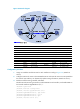
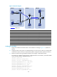
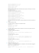
Figure 56 Network diagram
Device Interface IP address
Device
Interface IP address
Source 1 — 10.110.5.100/24 Router C POS5/1/0 192.168.1.2/24
Source 2 —
10.110.6.100/24
POS5/1/1 192.168.2.2/24
Router A GE2/1/1 10.110.5.1/24
Router D
GE2/1/1 10.110.3.1/24
S3/1/0 10.110.2.2/24 S3/1/0 10.110.4.1/24
Router B GE2/1/1 10.110.1.1/24
POS5/1/0 192.168.2.1/24
S3/1/0 10.110.2.1/24
Loop0
2.2.2.2/32
POS5/1/0 192.168.1.1/24 Loop10 4.4.4.4/32
Loop0 1.1.1.1/32
Loop20
10.1.1.1/32
Loop10 3.3.3.3/32
Router E
GE2/1/1 10.110.6.1/24
Loop20 10.1.1.1/32 S3/1/0 10.110.4.2/24
Configuration procedure
1. Assign an IP address and subnet mask to each interface according to Figure 56. (Details not
shown.)
2. Configure OSPF on the routers in the PIM-SM domain to make sure the routers are interoperable at
the network layer and they can dynamically update routing information. (Details not shown.)
3. Enable IP multicast routing, PIM-SM, and IGMP:
# Enable IP multicast routing on Router B, enable PIM-SM on each interface, and enable IGMP on
the host-side interface GigabitEthernet 2/1/1.
<RouterB> system-view
[RouterB] multicast routing-enable
[RouterB] interface gigabitethernet 2/1/1
[RouterB-GigabitEthernet2/1/1] igmp enable
[RouterB-GigabitEthernet2/1/1] pim sm
[RouterB-GigabitEthernet2/1/1] quit
[RouterB] interface serial 3/1/0
Loo
p0
L
oop20
Loop
20
Lo
op0
P
O
S
5
/
1
/
0
P
OS
5
/
1
/
0
P
O
S
5
/
1
/
1
P
O
S
5
/
1
/
0
S
3
/
1
/
0
S
3
/
1
/
0
S
3
/
1
/
0
S
3
/
1
/
0