
R3303-HP HSR6800 Routers IP Multicast Configuration Guide


229
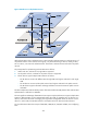
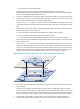
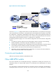
Figure 65 Receiver-side PE configuration
As shown in Figure 65, configure VPN instance B, create VPN instance A, and specify the share-group
on PE 3. Because PE 2 serves VPN A, create VPN instance A and specify the share-group on PE 2. After
the configuration, a share-MDT is established for VPN instance A. After receiving multicast packets from
Source 1, PE 1 encapsulates and forwards them to PE 2 and PE 3 along the share-MDT. PE 2 and PE 3
de-encapsulate and forward them to Receiver 1 and Receiver 2, respectively.
The following limitations apply to the source-side PE configuration and receiver-side PE configuration
schemes.
• In the VPN to which the multicast sources belong and the VPNs to which the receivers belong,
PIM-SM, BIDIR-PIM, or PIM-SSM is supported, but PIM-DM is not supported.
• The PIM modes, SSM group policies, and multicast source policies of the VPN to which the multicast
sources belong must be consistent with those of the VPNs to which the receivers belong.
• The RP must be in the same site of the same VPN as the multicast source.
• Multicasting cannot be implemented along multiple VPNs. For example, the multicast data from
VPN A cannot be forwarded to VPN C by VPN B.
Protocols and standards
draft-rosen-vpn-mcast-08, Multicast in MPLS/BGP IP VPNs
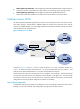
How MD-VPN works
This section describes how the MD-VPN technology is implemented, including the construction of a
share-MDT, delivery of multicast traffic based on the share-MDT, and implementation of multi-AS
MD-VPN.
For a VPN instance, multicast data transmission on the public network is transparent. The VPN data is
exchanged between the MTIs of the local PE and the remote PE. This implements the seamless