
R3303-HP HSR6800 Routers IP Multicast Configuration Guide


258
Item Network re
q
uirements
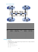
Multicast sources
and receivers
• In VPN a, S 1 is a multicast source, and R 2 is a receiver.
• In VPN b, S 2 is a multicast source, and R 1 is a receiver.
• For VPN a, the share-group address is 239.1.1.1, and the range of its
switch-group-pool addresses is 225.1.1.0 to 225.1.1.15.
• For VPN b, the share-group address is 239.4.4.4, and the range of its
switch-group-pool addresses is 225.4.4.0 to 225.4.4.15.
PE interfaces and
VPN instances they
belong to
• PE 1—GigabitEthernet 2/1/2 belongs to VPN instance a. GigabitEthernet 2/1/3
belongs to VPN instance b. Ethernet 1/1 and Loopback 1 belong to the public
network instance.
• PE 2—GigabitEthernet 2/1/1, GigabitEthernet 2/1/2, Loopback 1 and Loopback 2
belong to the public network instance.
• PE 3—GigabitEthernet 2/1/1, GigabitEthernet 2/1/2, Loopback 1 and Loopback 2
belong to the public network instance.
• PE 4—GigabitEthernet 2/1/2 belongs to VPN instance a. GigabitEthernet 2/1/3
belongs to VPN instance b. GigabitEthernet 2/1/1 and Loopback 1 belong to the
public network instance.
Unicast routing
protocols and MPLS
• Configure OSPF separately in AS 100 and AS 200, and configure OSPF between
the PEs and CEs.
• Establish BGP peer connections between PE 1, PE 2, PE 3 and PE 4 on their respective
Loopback 1 and exchange all VPN routes between them.
• Configure MPLS separately in AS 100 and AS 200.
IP multicast routing
• Enable IP multicast routing on the public network on PE 1, PE 2, PE 3 and PE 4.
• Enable IP multicast routing in VPN instance a on PE 1 and PE 4.
• Enable IP multicast routing in VPN instance b on PE 1 and PE 4.
• Enable IP multicast routing on CE a1, CE a2, CE b1, and CE b2.
IGMP
• Run IGMPv2 on GigabitEthernet 2/1/1 of CE a2.
• Run IGMPv2 on GigabitEthernet 2/1/1 of CE b2.
PIM
• Enable PIM-SM on all public network interfaces of PE 2 and PE 3.
• Enable PIM-SM on all public and private network interfaces of PE 1 and PE 4.
• Enable PIM-SM on all interfaces of CE a1, CE a2, CE b1, and CE b2.
• Configure Loopback 2 of PE 2 and PE 3 as a C-BSR and a C-RP for their respective AS
(to work for all multicast groups).
• Configure Loopback 0 of CE a1 as a C-BSR and a C-RP for VPN a (to work for all
multicast groups).
• Configure Loopback 0 of CE b1 as a C-BSR and a C-RP for VPN b (to work for all
multicast groups).
MSDP
• Establish an MSDP peering relationship between PE 2 and PE 3 on their respective
Loopback 1.