
R3303-HP HSR6800 Routers IP Multicast Configuration Guide

26
Configuring multicast VLANs
Overview
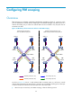
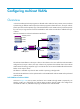
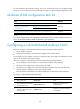
0 shows the traditional multicast programs-on-demand mode. When the hosts ( Host A, Host B, and Host
C) that belong to different VLANs require the multicast programs-on-demand service, the Layer 3 device
(Switch A) must forward a separate copy of the multicast data in each VLAN to the Layer 2 device (Switch
B). In this case, a large amount of network bandwidth is used and an extra burden is added to the Layer
3 device.
Multicast transmission without the multicast VLAN feature
The multicast VLAN feature on the Layer 2 device is the solution to this issue. After the multicast VLAN is
configured on the Layer 2 device, the Layer 3 device only replicates the multicast data in the multicast
VLAN instead of making a separate copy in each VLAN. This saves network bandwidth and lessens the
burden on the Layer 3 device.
This feature is available only when the SAP module is operating in bridge mode.
The multicast VLAN feature can be implemented in a sub-VLAN-based multicast VLAN and a port-based
multicast VLAN.
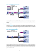
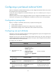
Sub-VLAN-based multicast VLAN
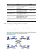
As shown in Figure 109, Host A, Host B, and Host C are in VLAN 2 through VLAN 4, respectively. On
Switch B, VLAN 10 is configured as a multicast VLAN, VLAN 2 through VLAN 4 are configured as
sub-VLANs of VLAN 10, and IGMP snooping is enabled for the multicast VLAN.
Source
Receiver
Host A
Multicast packets
VLAN 2
VLAN 3
VLAN 4
VLAN 2
VLAN 3
VLAN 4
Switch B
Receiver
Host B
Receiver
Host C
Switch A
IGMP querier