
R3303-HP HSR6800 Routers Layer 2 - LAN Switching Configuration Guide

164
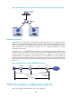
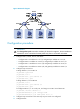
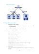
Figure 59 Network diagram
Configuration procedure
1. Configure Host A, Host B, and Host C:
{ Configure the IP addresses of Host A, Host B, and Host C as 1.1.1.1/24, 1.1.1.2/24, and
1.1.1.3 /24 , re sp e c t ive l y.
{ C o n f i g u r e t h e g a t e w a y I P a d d r e s s a s 1.1.1.11/24 for the hosts.
2. Configure Layer 2 Switch A:
# Assign Ethernet 1/1 to VLAN 11.
<L2_SwitchA> system-view
[L2_SwitchA] vlan 11
[L2_SwitchA-vlan11] port ethernet 1/1
[L2_SwitchA-vlan11] quit
# Assign Ethernet 1/2 to VLAN 12.
[L2_SwitchA] vlan 12
[L2_SwitchA-vlan12] port ethernet 1/2
[L2_SwitchA-vlan12] quit
# Assign Ethernet 1/3 to VLAN 13.
[L2_SwitchA] vlan 13
[L2_SwitchA-vlan13] port ethernet 1/3
[L2_SwitchA-vlan13] quit
# Configure Ethernet 1/7 as a trunk port, and assign it to VLANs 11 through 13.
[L2_SwitchA] interface ethernet 1/7
[L2_SwitchA-Ethernet1/7] port link-type trunk
[L2_SwitchA-Ethernet1/7] port trunk permit vlan 11 to 13
3. Configure Router:
# Create Ethernet subinterface GigabitEthernet4/0/1.10, and assign an IP address to the
subinterface.