
R3303-HP HSR6800 Routers Layer 2 - LAN Switching Configuration Guide


165
<Router> system-view
[Router] interface GigabitEthernet 4/0/1.10
[Router-GigabitEthernet4/0/1.10] ip address 1.1.1.11 255.255.255.0
# Enable Dot1q termination on GigabitEthernet 4/0/1.10, and configure the subinterface to
terminate VLAN-tagged packets whose Layer 1 VLAN ID is in the range of 11, 12, or 13.
[Router-GigabitEthernet4/0/1.10] vlan-type dot1q vid 11 to 13
[Router-GigabitEthernet4/0/1.10] quit
# Configure an IP address for GigabitEthernet4/0/2.
[Router] interface GigabitEthernet 4/0/2
[Router-GigabitEthernet4/0/2] ip address 1.1.2.11 255.255.255.0
4. Use the factory configuration of Layer 2 Switch B.
5. Assign each device in the server group an IP address on the network segment 1.1.2.0/24, and
configure the gateway IP address as 1.1.2.11/24.
Configuration example for Dot1q termination
supporting PPPoE server
Network requirements
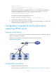
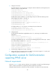
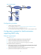
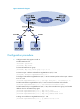
As shown in Figure 60, Host A, Host B, and Host C are connected to a switch, and belong to VLAN 11,
VLAN 12, and VLAN 13, respectively.
Configure Dot1q termination, so that the hosts can dial up to access the Internet.
Figure 60 Network diagram
Configuration procedure
1. Configure VLANs and Dot1q termination:
For the configuration procedure, see "Ambiguous Dot1q termination configuration example."