
R3303-HP HSR6800 Routers Layer 2 - LAN Switching Configuration Guide


168
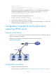
Figure 62 Network diagram
Configuration procedure
1. Configure Host A, Host B, and Host C:
{ Configure the IP addresses of Host A, Host B, and Host C as 1.1.1.1/24, 1.1.1.2/24, and
1.1.1.3 / 24 , r e s p e c t i v e l y.
{ Configure the gateway address as 1.1.1.11/24 for the hosts.
2. Configure Layer 2 Switch A:
# Assign Ethernet 1/1 to VLAN 11.
<L2_SwitchA> system-view
[L2_SwitchA] vlan 11
[L2_SwitchA-vlan11] port ethernet 1/1
[L2_SwitchA-vlan11] quit
# Assign Ethernet 1/2 to VLAN 12.
[L2_SwitchA] vlan 12
[L2_SwitchA-vlan12] port ethernet 1/2
[L2_SwitchA-vlan12] quit
# Assign Ethernet 1/3 to VLAN 13.
[L2_SwitchA] vlan 13
[L2_SwitchA-vlan13] port ethernet 1/3
[L2_SwitchA-vlan13] quit
# Configure Ethernet 1/7 as a hybrid port, and assign the port to VLANs 11 through 13 as a
tagged member.
[L2_SwitchA] interface ethernet 1/7
[L2_SwitchA-Ethernet1/7] port link-type hybrid
[L2_SwitchA-Ethernet1/7] port hybrid vlan 11 to 13 tagged
[L2_SwitchA-Ethernet1/7] port hybrid vlan 100 untagged