
R3303-HP HSR6800 Routers Layer 2 - LAN Switching Configuration Guide


169
3. Configure L2 Switch B:
# Configure Ethernet 1/2 as a trunk port, configure its PVID as VLAN 100, and assign the port to
VLANs 11 through 13 and VLAN 100.
<L2_SwitchB> system-view
[L2_SwitchB] interface ethernet 1/2
[L2_SwitchB-Ethernet1/2] port link-type trunk
[L2_SwitchB-Ethernet1/2] port trunk pvid vlan 100
[L2_SwitchB-Ethernet1/2] port trunk permit vlan 11 to 13 100
# Enable basic QinQ on Ethernet 1/2, and configure the port to add outer VLAN tag 100 to
packets tagged with VLANs 11 through 13.
[L2_SwitchB-Ethernet1/2] qinq enable
[L2_SwitchB-Ethernet1/2] qinq vid 100
[L2_SwitchB-Ethernet1/2-vid-100] raw-vlan-id inbound 11 to 13
[L2_SwitchB-Ethernet1/2-vid-100] quit
[L2_SwitchB-Ethernet1/2] quit
# Configure Ethernet 1/1 as a trunk port, and assign the port to VLAN 100.
[L2_SwitchB] interface ethernet 1/1
[L2_SwitchB-Ethernet1/1] port link-type trunk
[L2_SwitchB-Ethernet1/1] port trunk permit vlan 100
4. Configure Router:
# Create Ethernet subinterface GigabitEthernet 4/0/1.10, and assign an IP address to the
subinterface.
<Router> system-view
[Router] interface GigabitEthernet 4/0/1.10
[Router-GigabitEthernet4/0/1.10] ip address 1.1.1.11 255.255.255.0
# Configure GigabitEthernet 4/0/1.10 to terminate VLAN-tagged packets whose Layer 1 VLAN
ID is 100 and Layer 2 VLAN ID is 11, 12, or 13.
[Router-GigabitEthernet4/0/1.10] vlan-type dot1q vid 100 second-dot1q 11 to 13
[Router-GigabitEthernet4/0/1.10] quit
# Assign an IP address to GigabitEthernet4/0/2.
[Router] interface GigabitEthernet 4/0/2
[Router-GigabitEthernet4/0/2] ip address 1.1.2.11 255.255.255.0
5. Use the factory configuration of Layer 2 Switch C.
6. Assign each device in the server group an IP address on the network segment 1.1.2.0/24, and
configure the gateway IP address as 1.1.2.11/24.
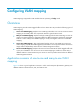
Configuration example for QinQ termination
supporting PPPoE server
Network requirements
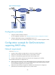
As shown in Figure 63, Host A, Host B, and Host C are connected to L2 Switch A and they belong to
VLAN 11, VLAN 12, and VLAN 13, respectively. QinQ is enabled on L2 Switch B.
Configure QinQ termination, so that Host A, Host B, and Host C can dial up to access the Internet.