
R3303-HP HSR6800 Routers Layer 2 - LAN Switching Configuration Guide


73
Task Command Remarks
Display historical information about port
role calculations for the specified MSTI or
all MSTIs (in IRF mode).
display stp [ instance instance-id ] history
[ chassis chassis-number slot slot-number ]
[ | { begin | exclude | include }
regular-expression ]
Available in any
view.
Display statistics about TC/TCN BPDUs
sent and received by all ports in the
specified MSTI or all MSTIs (in standalone
mode).
display stp [ instance instance-id ] tc [ slot
slot-number ] [ | { begin | exclude |
include } regular-expression ]
Available in any
view.
Display statistics about TC/TCN BPDUs
sent and received by all ports in the
specified MSTI or all MSTIs (in IRF mode).
display stp [ instance instance-id ] tc
[ chassis chassis-number slot slot-number ]
[ | { begin | exclude | include }
regular-expression ]
Available in any
view.
Display spanning tree status and statistics
(in standalone mode).
display stp [ instance instance-id ]
[ interface interface-list | slot slot-number ]
[ brief ] [ | { begin | exclude | include }
regular-expression ]
Available in any
view.
Display spanning tree status and statistics
(in IRF mode).
display stp [ instance instance-id ]
[ interface interface-list | chassis
chassis-number slot slot-number ] [ brief ]
[ | { begin | exclude | include }
regular-expression ]
Available in any
view.
Display MST region configuration
information in effect.
display stp region-configuration [ |
{ begin | exclude | include }
regular-expression ]
Available in any
view.
Display root bridge information for all
MSTIs.
display stp root [ | { begin | exclude |
include } regular-expression ]
Available in any
view.
Clear spanning tree statistics. reset stp [ interface interface-list ]
Available in user
view.
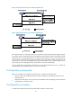
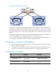
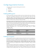
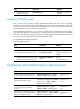
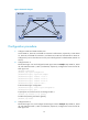
MSTP configuration example
Network requirements
As shown in Figure 25:
• All devices on the network are in the same MST region. Router A and Router B work at the
distribution layer. Router C and Router D work at the access layer.
• Configure MSTP so that packets of different VLANs are forwarded along different spanning trees:
Packets of VLAN 10 are forwarded along MSTI 1, those of VLAN 30 are forwarded along MSTI 3,
those of VLAN 40 are forwarded along MSTI 4, and those of VLAN 20 are forwarded along MSTI
0.
• VLAN 10 and VLAN 30 are terminated on distribution layer devices, and VLAN 40 is terminated
on access layer devices. The root bridges of MSTI 1 and MSTI 3 are Router A and Router B,
respectively, and the root bridge of MSTI 4 is Router C.