
R3303-HP HSR6800 Routers Layer 3 - IP Routing Configuration Guide


119
Summary Count : 1
Destination: 4.4.4.4/32
Protocol: OSPF Process ID: 1
Preference: 10 Cost: 1
IpPrecedence: QosLcId:
NextHop: 13.13.13.2 Interface: GigabitEthernet2/1/2
BkNextHop: 12.12.12.2 BkInterface: GigabitEthernet2/1/1
RelyNextHop: 0.0.0.0 Neighbor : 0.0.0.0
Tunnel ID: 0x0 Label: NULL
BKTunnel ID: 0x0 BKLabel: NULL
State: Active Adv Age: 00h01m27s
Tag: 0
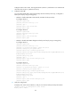
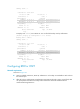
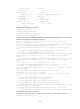
# Display route 1.1.1.1/32 on Router D. You can find the backup next hop information.
[RouterD] display ip routing-table 1.1.1.1 verbose
Routing Table : Public
Summary Count : 1
Destination: 1.1.1.1/32
Protocol: OSPF Process ID: 1
Preference: 10 Cost: 1
IpPrecedence: QosLcId:
NextHop: 13.13.13.1 Interface: GigabitEthernet2/1/2
BkNextHop: 24.24.24.2 BkInterface: GigabitEthernet2/1/1
RelyNextHop: 0.0.0.0 Neighbor : 0.0.0.0
Tunnel ID: 0x0 Label: NULL
BKTunnel ID: 0x0 BKLabel: NULL
State: Active Adv Age: 00h01m27s
Tag: 0
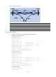
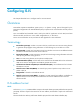
Configuring BFD for OSPF
Network requirements
As shown in Figure 33:
• OSPF is enabled on Router A, Router B, and Router C so that they are reachable to each other at
the network layer.
• After the link over which Router A and Router B communicate through a Layer 2 switch fails, BFD
can quickly detect the failure and notify OSPF of the failure. Router A and Router B then
communicate through Router C.