
R3303-HP HSR6800 Routers Layer 3 - IP Routing Configuration Guide

177
IS-IS NSR configuration example
Network requirements
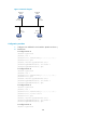
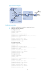
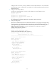
Router S, Router A, and Router B belong to the same IS-IS routing domain as illustrated in Figure 54.
Enable IS-IS NSR on Router S to ensure correct routing when an active/standby switchover occurs on
Router S.
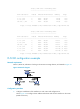
Figure 54 Network diagram
Configuration procedure
1. Configure IP addresses for the interfaces on each router and configure IS-IS:
Follow Figure 54 to c
onfigure the IP address and subnet mask of each interface on the routers.
(Details not shown.)
Configure IS-IS on the routers, ensuring that Router S, Router A, and Router B can communicate
with each other at Layer 3, and dynamic route update can be implemented among them with IS-IS.
(Details not shown.)
2. Configure IS-IS NSR:
# Enable IS-IS NSR on Router S.
<RouterS> system-view
[RouterS] isis 1
[RouterS-isis-1] non-stop-routing
[RouterS-isis-1] non-stop-routing interval 30
[RouterS-isis-1] return
3. Verify the configuration:
After Router S establishes neighbor relationships with Router A and Router B, they start to
exchange routing information. After network convergence, perform an active/standby switchover
on Router S. During the switchover period, use the display isis peer command to check the
neighbor relationships between Router A and Router S and between Router B and Router S; use the
display isis route command to check if routes from Router A to the loopback interface on Router B
and from Router B to the loopback interface on Router A exist.
# Perform an active/standby switchover on Router S.
<RouterS> system-view
[RouterS] slave switchover enable
[RouterS] slave switchover
Caution!!! Confirm to switch slave to master? [Y/N]:Y
# Display IS-IS neighbors and routes on Router A.
<RouterA> display isis peer
Peer information for ISIS(1)
----------------------------