
R3303-HP HSR6800 Routers Layer 3 - IP Routing Configuration Guide

13
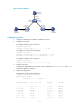
BFD for static routes configuration example (direct next hop)
Network requirements
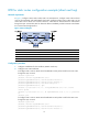
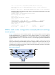
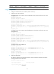
In Figure 3, configure a static route to subnet 120.1.1.0/24 on Router A, configure a static route to subnet
121.1.1.0/24 on Router B, and enable BFD for both routes. Configure a static route to subnet 120.1.1.0/24
and a static route to subnet 121.1.1.0/24 on Router C. When the link between Router A and Router B
through the Layer 2 switch fails, BFD can detect the failure immediately and inform Router A and Router
B to communicate through Router C.
Figure 3 Network diagram
Device Interface IP address
Device
Interface
IP address
Router A GE2/1/1 12.1.1.1/24
Router B
GE2/1/1 12.1.1.2/24
GE2/1/2 10.1.1.102/24 GE2/1/2 13.1.1.1/24
Router C GE2/1/1 10.1.1.100
/
24
GE2/1/2 13.1.1.2/24
Configuration procedure
1. Configure IP addresses for the interfaces. (Details not shown.)
2. Configure static routes and BFD:
# Configure static routes on Router A and enable BFD control packet mode for the static route
through the Layer 2 switch.
<RouterA> system-view
[RouterA] interface GigabitEthernet 2/1/1
[RouterA-GigabitEthernet2/1/1] bfd min-transmit-interval 500
[RouterA-GigabitEthernet2/1/1] bfd min-receive-interval 500
[RouterA-GigabitEthernet2/1/1] bfd detect-multiplier 9
[RouterA-GigabitEthernet2/1/1] quit
[RouterA] ip route-static 120.1.1.0 24 GigabitEthernet 2/1/1 12.1.1.2 bfd
control-packet
[RouterA] ip route-static 120.1.1.0 24 GigabitEthernet 2/1/2 10.1.1.100 preference
65
[RouterA] quit
# Configure static routes on Router B and enable BFD control packet mode for the static route
through the Layer 2 switch.
<RouterB> system-view
[RouterB] interface GigabitEthernet 2/1/1
[RouterB-GigabitEthernet2/1/1] bfd min-transmit-interval 500
[RouterB-GigabitEthernet2/1/1] bfd min-receive-interval 500