
R3303-HP HSR6800 Routers Layer 3 - IP Routing Configuration Guide

15
*Jul 27 10:18:19:172 2007 RouterA BFD/7/EVENT:Receive Delete-sess,
[Src:12.1.1.1,Dst:12.1.1.2,GigabitEthernet2/1/1,Ctrl], Direct, Instance:0x0,
Proto:STATIC
#*Jul 27 10:18:19:172 2007 RouterA BFD/7/EVENT:Notify driver to stop receiving bf
# Display the static route information again. Router A communicates with Router B over the static
route passing Router C now.
<RouterA> display ip routing-table protocol static
Public Routing Table : Static
Summary Count : 2
Static Routing table Status : <Active>
Summary Count : 1
Destination/Mask Proto Pre Cost NextHop Interface
120.1.1.0/24 Static 65 0 10.1.1.100 GE2/1/2
Static Routing table Status : < Inactive>
Summary Count : 1
Destination/Mask Proto Pre Cost NextHop Interface
120.1.1.0/24 Static 60 0 12.1.1.2 GE2/1/1
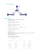
BFD for static routes configuration example (indirect next hop)
Network requirements
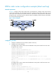
In Figure 4, Router A has a route to interface Loopback 1 (2.2.2.9/32) on Router B, with the outgoing
interface GigabitEthernet 2/1/1. Router B has a route to interface Loopback 1 (1.1.1.9/32) on Router A,
with the outgoing interface GigabitEthernet 2/1/1. Router D has a route to 1.1.1.9/32, with the outgoing
interface GigabitEthernet 2/1/1, and a route to 2.2.2.9/32, with the outgoing interface GigabitEthernet
2/1/2.
Configure a static route to subnet 120.1.1.0/24 on Router A, configure a static route to subnet
121.1.1.0/24 on Router B, and enable BFD for both routes. Configure a static route to subnet 120.1.1.0/24
and a static route to subnet 121.1.1.0/24 on both Router C and Router D. When the link between Router
A and Router B through Router D fails, BFD can detect the failure immediately and Router A and Router
B can communicate through Router C.
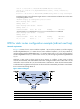
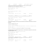
Figure 4 Network diagram
Device Interface IP address
Device
Interface
IP address
Router A GE2/1/1 12.1.1.1/24 Router B GE2/1/1 11.1.1.2/24
GE2/1/2 10.1.1.102
/
24
GE2/1/2 13.1.1.1/24
Loop1 1.1.1.9/32
Loop1
2.2.2.9/32