
R3303-HP HSR6800 Routers Layer 3 - IP Routing Configuration Guide
283
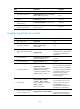
[RouterA-Serial2/2/1] ip address 1.1.3.1 255.255.255.0
2. Configure Router B:
# Configure the IP address of the serial interface.
<RouterB> system-view
[RouterB] interface serial 2/2/0
[RouterB-Serial2/2/0] ip address 1.1.2.2 255.255.255.0
[RouterB-Serial2/2/0] quit
3. Configure Router C:
# Configure the IP address of the serial interface.
<RouterC> system-view
[RouterC] interface serial 2/2/1
[RouterC-Serial2/2/1] ip address 1.1.3.2 255.255.255.0
[RouterC-Serial2/2/1] quit
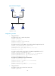
4. Verify the configuration:
# Telnet to Router B (1.1.2.2/24) from Router A. The operation succeeds.
# Telnet to Router C (1.1.3.2/24) from Router A. The operation fails.
# Ping Router C (1.1.3.2/24) from Router A. The operation succeeds.
Telnet uses TCP, and ping uses ICMP. The preceding results show that all TCP packets of Router A
are forwarded through Serial 2/2/0, and other packets are forwarded through Serial 2/2/1. The
local PBR configuration is effective.
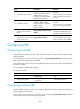
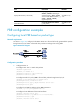
Configuring interface PBR based on packet type
Network requirements
As shown in Figure 85, configure interface PBR on Router A to forward all TCP packets received on
GigabitEthernet 2/1/1 through Serial 2/2/0. Router A forwards other packets according to the routing
table.