
R3303-HP HSR6800 Routers Layer 3 - IP Routing Configuration Guide


288
success : POLICY_ROUTEMAP : lab1, Node : 20, next-hop : 151.1.1.2
*Jun 7 12:06:49:627 2009 RouterA PBR/7/POLICY-ROUTING: IP policy based routing
success : POLICY_ROUTEMAP : lab1, Node : 20, next-hop : 151.1.1.2
*Jun 7 12:06:50:627 2009 RouterA PBR/7/POLICY-ROUTING: IP policy based routing
success : POLICY_ROUTEMAP : lab1, Node : 20, next-hop : 151.1.1.2
The preceding information shows that Router A sets the next hop for the received packets to
151.1.1.2 according to PBR. The packets are forwarded through Serial 2/2/1.
Configuring interface PBR based on reverse input interface
Network requirements
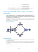
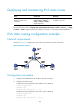
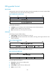
As shown in Figure 87, Router A (gateway) is connected to the public network through two interfaces
(Serial 2/2/0 and Serial 2/2/1). PC on the public network sends a request packet to the HTTP server on
the private network. Suppose the packet is received by Serial 2/2/0 on Router A and then is forwarded
to the HTTP server through GigabitEthernet 2/1/1.
It is required that the response packet from the private network should enter Router A through
GigabitEthernet 2/1/1 and leave Router A through the reverse input interface Serial 2/2/0 (the
interface that receives the request packet).
Figure 87 Network diagram
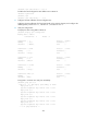
Configuration procedure
# Configure IP addresses for the interfaces on Router A and make sure that Router A can reach the public
network. (Details not shown.)
# Configure an NAT internal server on interface Serial 2/2/0, and specify 2.1.1.100/16 (on the same
network segment as the IP address of Serial 2/2/0 on Router A) as the public address of the HTTP server
192.168.1.2/24.
<RouterA> system-view
[RouterA] interface serial 2/2/0
[RouterA-Serial2/2/0] nat server protocol tcp global 2.1.1.100 www inside 192.168.1.2 www
[RouterA-Serial2/2/0] quit