
R3303-HP HSR6800 Routers Layer 3 - IP Routing Configuration Guide


289
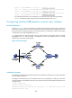
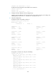
# Configure an NAT internal server on interface Serial 2/2/1, and specify 2.2.1.100/16 (on the same
network segment as the IP address of Serial 2/2/1 on Router A) as the public address of the HTTP server
192.168.1.2/24.
[RouterA] interface serial 2/2/1
[RouterA-Serial2/2/1] nat server protocol tcp global 2.2.1.100 www inside 192.168.1.2 www
[RouterA-Serial2/2/1] quit
# Configure Node 10 for policy test to forward packets matching the reverse input interface Serial
2/2/0 to the next hop 2.1.1.2/16.
[RouterA] policy-based-route test permit node 10
[RouterA-pbr-test-10] if-match reverse-input-interface serial 2/2/0
[RouterA-pbr-test-10] apply ip-address next-hop 2.1.1.2
[RouterA-pbr-test-10] quit
# Apply policy test to GigabitEthernet 2/1/1 on Router A.
[RouterA] interface GigabitEthernet 2/1/1
[RouterA-GigabitEthernet2/1/1] ip policy-based-route test
Configuring interface PBR on a VLAN interface
Network requirements
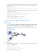
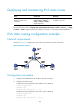
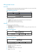
See Figure 88. Router A is configured with SAP modules. Configure Router A to operate in gateway
mode, create VLAN 100 and VLAN 200 on it, and configure interface PBR on VLAN-interface 200 so
that packets from VLAN 200 to VLAN 100 are forwarded through GigabitEthernet 2/0/2.
Host A belongs to VLAN 100, and Host B belongs to VLAN 200. VLAN 100 and VLAN 200 have a
route to each other.
Figure 88 Network diagram
Configuration procedure
# Enable gateway mode on Router A, and configure GigabitEthernet 2/0/0 and GigabitEthernet
2/0/1 to operate in bridge mode.
<RouterA> system-view
[RouterA] gateway-mode
[RouterA] interface gigabitethernet2/0/0
[RouterA-gigabitethernet2/0/0] port link-mode bridge
[RouterA-gigabitethernet2/0/0] quit
[RouterA] interface gigabitethernet2/0/1