
R3303-HP HSR6800 Routers Layer 3 - IP Services Configuration Guide


92
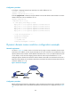
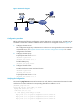
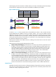
Figure 43 Network diagram
Configuration procedure
Before performing the following configuration, assume that Device A, the DNS server, and the host are
reachable to each other and the IP addresses of the interfaces are configured as shown in Figure 43.
1. Conf
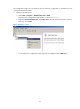
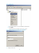
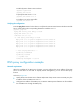
igure the DNS server:
This configuration might vary with DNS servers. When a PC running Windows Server 2000 acts
as the DNS server, see "Dynamic domain name resolution c
onfiguration example" for related
configuration information.
2. Configure the DNS proxy:
# Specify the DNS server 4.1.1.1.
<RouterA> system-view
[RouterA] dns server 4.1.1.1
# Enable DNS proxy.
[RouterA] dns proxy enable
3. Configure the DNS client:
# Enable the domain name resolution function.
<RouterB> system-view
[RouterB] dns resolve
# Specify the DNS server 2.1.1.2.
[RouterB] dns server 2.1.1.2
Verifying the configuration
# Execute the ping host.com command on Router B to verify that the communication between the router
and the host is normal and that the corresponding destination IP address is 3.1.1.1.
[RouterB] ping host.com
Trying DNS resolve, press CTRL_C to break
Trying DNS server (2.1.1.2)
PING host.com (3.1.1.1):
56 data bytes, press CTRL_C to break
Reply from 3.1.1.1: bytes=56 Sequence=1 ttl=126 time=3 ms
Reply from 3.1.1.1: bytes=56 Sequence=2 ttl=126 time=1 ms
Reply from 3.1.1.1: bytes=56 Sequence=3 ttl=126 time=1 ms