
R3303-HP HSR6800 Routers Layer 3 - IP Services Configuration Guide

107
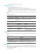
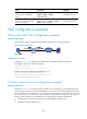
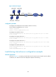
Figure 50 Network diagram
Configuration procedure
# Configure the IP addresses for the interfaces. (Details not shown.)
# Add members to internal server group 0.
<Router> system-view
[Router] nat server-group 0
[Router-nat-server-group-0] inside ip 10.110.10.1 port 21
[Router-nat-server-group-0] inside ip 10.110.10.2 port 21
[Router-nat-server-group-0] inside ip 10.110.10.3 port 21
[Router-nat-server-group-0] quit
# Associate internal server group 0 with GigabitEthernet 3/1/2 so that hosts in the server group can
provide FTP services.
[Router] interface gigabitethernet 3/1/2
[Router-GigabitEthernet3/1/2] nat server protocol tcp global 202.38.1.1 ftp inside
server-group 0
[Router-GigabitEthernet3/1/2] quit
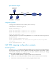
NAT DNS mapping configuration example
Network requirements
As shown in Figure 51, a company provides Web and FTP services to external users, and uses internal IP
network segment 10.110.0.0/16. The IP addresses of the Web and FTP servers are 10.110.10.1/16 and
10.110.10.2/16, respectively. The company has three public addresses 202.38.1.1/24 through
202.38.1.3/24. The DNS server is at 202.38.1.4/24.
• The public IP address 202.38.1.2 is used to provide services to external users.
• External users can use the public address or domain name of internal servers to access them.
• Internal users can access the internal servers by using their domain names.
FTP server 2
10.110.10.2/16
FTP server 1
10.110.10.1/16
FTP server 3
10.110.10.3/16
Host
Internet
GE3/1/1
10.110.10.10/16
GE3/1/2
202.38.1.1/16
Router