
R3303-HP HSR6800 Routers Layer 3 - IP Services Configuration Guide

267
Ste
p
Command
Remarks
12. Return to system view.
quit N/A
13. Configure a route for packet
forwarding through the
tunnel.
See Layer 3—IP Routing
Configuration Guide.
Each end of the tunnel must have a
route (static or dynamic) through
the tunnel to the other end.
For information about tunnel interfaces and related configurations, see "Configuring tunneling."
For more information about commands interface tunnel, tunnel-protocol, source, destination, and
encapsulation-limit, see Layer 3—IP Services Command Reference.
Displaying GRE
Task Command Remarks
Display information about a
specific or all tunnel interfaces.
display interface [ tunnel ] [ brief
[ down ] ] [ | { begin | exclude |
include } regular-expression ]
display interface tunnel number
[ brief [ description ] ] [ | { begin |
exclude | include }
regular-expression ]
Available in any view.
Display IPv6 information about a
tunnel interface.
display ipv6 interface tunnel
[ number ] [ brief [ description ] ] [ |
{ begin | exclude | include }
regular-expression ]
Available in any view.
For more information about commands display interface tunnel and display ipv6 interface tunnel, see
Layer 3—IP Services Command Reference.
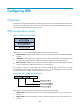
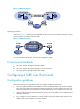
GRE over IPv4 tunnel configuration example
Network requirements
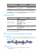
As shown in Figure 114 , Router A and Router B are interconnected through the Internet. Two private IPv4
subnets Group 1 and Group 2 are interconnected through a GRE tunnel between the two routers.
Figure 114 Network diagram
Configuration procedure
Before the configuration, make sure Router A and Router B can reach each other.
1. Configure Router A: