
R3303-HP HSR6800 Routers Layer 3 - IP Services Configuration Guide


280
Basic P2MP GRE tunnel configuration example
Network requirements
A company has a network at the headquarters and each of its branches. Implement communication
between the headquarters and the branches through GRE, but forbid communication between the
branches. Figure 121 sh
ows a simplified scenario, where there is only one branch.
• Router A is the gateway at the headquarters, and Router B is the gateway of the branch.
• Host A is an internal user at the headquarters and Host B is an internal user at the branch. A GRE
tunnel is established between Router A and Router B to implement intercommunication between
Host A and Host B.
If you use P2P GRE tunnels, the number of GRE tunnels to be configured is the same as that of the
branches. To simplify the configuration at the headquarters, you can create a P2MP GRE tunnel interface
on Router A, and configure a GRE over IPv4 tunnel interface on Router B.
This example uses Router B to illustrate the branch gateway configuration. The configuration on other
branch gateways is similar.
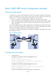
Figure 121 Network diagram
Configuration procedure
1. Configure Router A:
# Configure an IP address for interface GigabitEthernet 3/0/1.
<RouterA> system-view
[RouterA] interface gigabitethernet 3/0/1
[RouterA–GigabitEthernet3/0/1] ip address 11.1.1.1 255.255.255.0
[RouterA–GigabitEthernet3/0/1] quit
# Configure an IP address for interface GigabitEthernet 3/0/2.
[RouterA] interface gigabitethernet 3/0/2
[RouterA–GigabitEthernet 3/0/2] ip address 192.168.11.1 255.255.255.0
[RouterA–GigabitEthernet 3/0/2] quit
# Create a tunnel interface Tunnel 0 and configure an IP address for it.