
R3303-HP HSR6800 Routers Layer 3 - IP Services Configuration Guide


282
# View tunnel entry information on Router A again. Because the branch has initiated tunnel
establishment by sending packets to the headquarters, a tunnel entry should be installed, as shown in the
following output information:
[RouterA] display gre p2mp tunnel-table interface tunnel 0
Dest Addr Mask Tunnel Dest Addr Gre Key
192.168.12.0 255.255.255.0 11.1.1.2
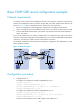
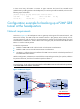
Configuration example for backing up a P2MP GRE
tunnel at the headquarters
Network requirements
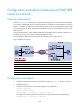
As shown in Figure 122, the headquarters uses two gateways at the egress of the internal network, with
Router B for backup. Two GRE tunnels are created on Router C (the gateway at the branch): one for
connecting Router A and the other for connecting Router B. Packets are forwarded along the tunnel
between Router A and Router C. When a failure occurs along this path, the tunnel between Router B and
Router C is used to transmit packets.
To meet the requirements:
• Establish a P2MP GRE tunnel with the branch on both Router A and Router B.
• Establish a GRE over IPv4 tunnel between Router A and Router B.
• On Router A, configure the tunnel interface of the GRE over IPv4 tunnel as the backup interface of
the P2MP GRE tunnel interface.
With this configuration, when Router A cannot find the corresponding tunnel entry for a packet, it delivers
the packet to Router B, which then forwards the packet to Router C.
NOTE:
To avoid looping, do not configure the tunnel interface of the GRE over IPv4 tunnel as the backup interface
of the P2MP GRE tunnel interface on Router B.
Figure 122 Network diagram
GE3/1/2
GE3/1/1
GE3/1/1
Router A
Router B
(Backup gateway)
IPv4 network
Router C
GE3/1/2
GE3/1/3
GE3/1/3
GE3/1/1 GE3/1/2
Tunnel0
Tunnel0
Tunnel0
Tunnel1
Tunnel1
Tunnel1
Host A
Host B
Host C
GRE P2MP tunnel
GRE over IPv4 tunnel
Headquarters
Branch