
R3303-HP HSR6800 Routers Layer 3 - IP Services Configuration Guide

286
Configuration example for backing up a P2MP GRE
tunnel at a branch
Network requirements
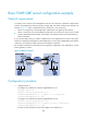
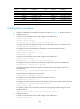
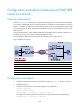
As shown in Figure 123, a branch uses two gateways at the egress of the internal network, with Router
C for backup. A P2MP GRE tunnel is created on Router A, the gateway at the headquarters, allowing
Router A to establish two GRE tunnels to the branch network, one for connecting Router B and the other
for connecting Router C. Router A decides which GRE tunnel to use to send packets to the hosts on the
branch network.
To meet the requirements, configure different GRE keys for the GRE tunnels on Router B and Router C, so
that Router A can choose a tunnel according to the GRE key values.
In this example, the GRE tunnel between Router A and Router B has a higher priority.
Figure 123 Network diagram
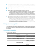
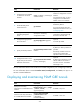
Device Interface IP Address
Device
Interface
IP Address
Router A GE3/1/1 11.1.1.1/24 Router B GE3/1/1 11.1.1.2/24
GE3/1/2 172.17.17.1/24
GE3/1/2 192.168.1.2
/
24
Tunnel0 192.168.22.1/24
Tunnel0
192.168.22.2/24
Router C GE3/1/1 11.1.1.3/24 Router C Tunnel0 192.168.22.3/24
GE3/1/2 192.168.1.3
/
24
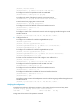
Configuration procedure
1. Configure IP addresses and masks for interfaces according to Figure 123. (Details not shown.)
2. Configure Router A:
# Create a tunnel interface Tunnel 0 and configure an IP address for it.
<RouterA> system-view
[RouterA] interface tunnel 0
[RouterA-Tunnel0] ip address 192.168.22.1 255.255.255.0
# Configure the tunnel encapsulation mode of the tunnel interface Tunnel 0 as P2MP GRE.
[RouterA-Tunnel0] tunnel-protocol gre p2mp