HP HSR6800 Routers MPLS Configuration Guide Part number: 5998-4494 Software version: HSR6800-CMW520-R3303P05 Document version: 6PW105-20140507
Legal and notice information © Copyright 2014 Hewlett-Packard Development Company, L.P. No part of this documentation may be reproduced or transmitted in any form or by any means without prior written consent of Hewlett-Packard Development Company, L.P. The information contained herein is subject to change without notice.
Contents Configuring basic MPLS ·············································································································································· 1 Overview············································································································································································ 1 Basic concepts ·········································································································································
Configuring MPLS TE ················································································································································· 40 Overview········································································································································································· 40 Basic concepts ···················································································································································
Configuring FRR ····························································································································································· 77 Enabling FRR on the ingress node of a protected LSP ······················································································· 78 Configuring a bypass tunnel on its PLR ··············································································································· 78 Configuring node protection ··········
Creating a Martini VC on a Layer 3 interface ································································································· 170 Creating a Martini VC for a service instance ·································································································· 170 Configuring Kompella MPLS L2VPN ·························································································································· 172 Configuring BGP L2VPN capability ·························
MPLS L3VPN routing information advertisement ······························································································ 254 Inter-AS VPN ························································································································································ 255 Carrier's carrier ··················································································································································· 258 Nested VPN ·················
Example 1 for configuring MPLS L3VPN FRR ··································································································· 389 Example 2 for configuring MPLS L3VPN FRR ··································································································· 391 Configuring IPv6 MPLS L3VPN ······························································································································ 394 Overview······················································
Configuring basic MPLS Overview Multiprotocol Label Switching (MPLS) enables connection-oriented label switching on connectionless IP networks. It integrates both the flexibility of IP routing and the level of simplicity of Layer 2 switching. MPLS has the following advantages: • MPLS forwards packets according to short- and fixed-length labels, instead of Layer 3 header analysis and complicated routing table lookup, enabling highly-efficient and fast data forwarding on backbone networks.
• S—One bit in length. MPLS supports multiple levels of labels. This field indicates whether a label is at the bottom of the label stack. A value of 1 indicates that the label is at the bottom of the label stack. • TTL—Eight bits in length. Like the homonymous IP header field, it is used to prevent loops. LSR A label switching router (LSR) is a fundamental component on an MPLS network. LSRs support label distribution and label swapping.
MPLS network structure Figure 3 Diagram of the MPLS network structure LSRs in the same routing or administrative domain form an MPLS domain. An MPLS domain consists of the following types of LSRs: • Ingress LSRs receive and label packets coming into the MPLS domain. • Transit LSRs forward packets along LSPs to their egress LERs according to the labels. • Egress LSRs remove labels from packets and forward the packets to their destination networks.
NOTE: In this document, the term "label distribution protocols" refers to all protocols for label distribution. The term "LDP" refers to the RFC 5036 LDP. A dynamic LSP is established in the following procedure: A downstream LSR classifies FECs according to destination addresses. It assigns a label to a FEC, and distributes the FEC-label binding to its upstream LSR, which then establishes an LFIB entry for the FEC according to the binding information.
Figure 5 Label advertisement modes DU mode Ingress 2) Unsolicitely distribute a label mapping for the FEC to the upstream. 1) Unsolicitely distribute a label mapping for a FEC to the upstream. Transit Egress 1) Send a label request for a FEC to the downstream. 2) Send a label request for the FEC to the downstream. DoD mode 4) Distribute a label mapping for the FEC to the upstream upon receiving the request. 3) Distribute a label mapping for the FEC to the upstream upon receiving the request.
Figure 6 Independent label distribution control mode • In ordered mode, an LSR distributes its label binding for a FEC upstream only when it receives a label binding for the FEC from its downstream or it is the egress of the FEC. In Figure 5, label distribution control is in ordered mode. If the label advertisement mode is DU, an LSR distributes a label upstream only when it receives a label binding for the FEC from its downstream.
• Incoming Label Map—ILM maps each incoming label to a set of NHLFEs. It is used to forward labeled packets. When an LSR receives a labeled packet, it looks for the corresponding ILM entry. If the Token value of the ILM entry is not null, the LSR looks for the corresponding NHLFE entry to determine the label operation to be performed. FTN and ILM are associated with NHLFE through Token.
node needs to do two forwarding table lookups to forward a packet: looking up the LFIB twice or looking up the LFIB and the FIB once each. The penultimate hop popping (PHP) feature can pop the label at the penultimate node to relieve the egress of the label operation burden. PHP is configured on the egress node.
{ Extended discovery mechanism—Discovers indirectly connected LDP peers and establishes targeted hello adjacencies. An LSR periodically sends LDP Hello messages to a given IP address so that the LSR with the IP address can discover the LDP peer.
Protocols • RFC 3031, Multiprotocol Label Switching Architecture • RFC 3032, MPLS Label Stack Encoding • RFC 5036, LDP Specification MPLS configuration task list Task Remarks Enabling the MPLS function Required. Configuring a static LSP Required. Establishing dynamic LSPs through LDP Maintaining LDP sessions Managing and optimizing MPLS forwarding Configuring MPLS statistics collection and reading Inspecting LSPs Configuring MPLS LDP capability Required.
Task Remarks Configuring MPLS LSP tracert Enabling MPLS trap Optional. Optional. Enabling the MPLS function In an MPLS domain, you must enable MPLS on all routers before you can configure other MPLS features. Before you enable MPLS, complete the following tasks: • Configure link layer protocols to ensure the connectivity at the link layer. • Assign IP addresses to interfaces so that all neighboring nodes can reach each other at the network layer.
Make sure the ingress LSR has a route to the FEC destination. This is not required on the transit LSRs and egress LSR. • Configuration guidelines Follow these guidelines when you configure a static LSP: • Do not specify a P2MP interface (such as a P2MP-type ATM subinterface or frame relay subinterface) as the outgoing interface. Otherwise, the static LSP cannot be up.
Step Command Remarks Optional. By default, the LDP LSR ID is the same as the MPLS LSR ID. You need to perform this task only in a multi-VPN context to make sure that different LDP instances have different LDP LSR IDs if their address spaces overlap. Otherwise, TCP connections cannot be established. 3. Configure the LDP LSR ID. lsr-id lsr-id 4. Return to system view. quit N/A 5. Enter interface view. interface interface-type interface-number N/A 6. Enable LDP capability for the interface.
Step Command Remarks Optional. Configure the LDP transport address. 5. mpls ldp transport-address { ip-address | interface } The default takes the value of the MPLS LSR ID. The specified IP address must be the IP address of an interface on the device. Configuring remote LDP session parameters LDP sessions established between remote LDP peers are remote LDP sessions. Remote LDP sessions are mainly used in Martini MPLS L2VPN, Martini VPLS, and MPLS LDP over MPLS TE.
Step Set the targeted Keepalive timer. 6. Command Remarks mpls ldp timer keepalive-hold value Optional. The default value is 45 seconds. Optional. Configure the LDP transport address. 7. mpls ldp transport-address ip-address The default takes the value of the MPLS LSR ID. The specified IP address must be the IP address of an interface on the device.
Step Command Remarks 1. Enter system view. system-view N/A 2. Enter MPLS view. mpls N/A Optional. By default, only host routes with 32-bit masks can trigger establishment of LSPs. 3. Configure the LSP establishment triggering policy. lsp-trigger [ vpn-instance vpn-instance-name ] { all | ip-prefix prefix-name } If the vpn-instance vpn-instance-name option is specified, the command configures an LSP establishment triggering policy for the specified VPN.
Configuring LDP loop detection LSPs established in an MPLS domain might be looping. The LDP loop detection mechanism can detect looping LSPs and prevent LDP messages from looping forever. LDP loop detection can be in either of the following modes: • Maximum hop count—A label request message or label mapping message carries information about its hop count, which increments by 1 for each hop.
Configuring LDP MD5 authentication LDP sessions are established based on TCP connections. To improve the security of LDP sessions, you can configure MD5 authentication for the underlying TCP connections, so that the TCP connections can be established only if the peers have the same authentication password. IMPORTANT: To establish an LDP session successfully between two LDP peers, make sure their LDP MD5 authentication settings are the same. To configure LDP MD5 authentication: Step Command Remarks 1.
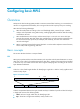
Label advertisement control Label advertisement control is for filtering label bindings to be advertised. A downstream LSR advertises only the label bindings of the specified FECs to the specified upstream LSR. As shown in Figure 9, downstream device LSR A advertises to upstream device LSR B only label bindings with FEC destinations permitted by prefix list B, and advertises to upstream device LSR C only label bindings with FEC destinations permitted by prefix list C.
Configuring BFD for MPLS LDP Use BFD to help MPLS promptly detect a neighbor failure or link failure between two remote LDP peers. BFD can help MPLS LDP detect communication failures only between remote LDP peers. For configuration examples, see "Configuring VPLS." For more information about BFD, see High Availability Configuration Guide. To configure BFD for MPLS LDP: Step Command Remarks 1. Enter system view. system-view N/A 2. Enter MPLS LDP remote peer view.
• If fragmentation is allowed, the LSR removes the label stack from the packet, fragments the IP packet (the length of a fragment is the MPLS MTU minus the length of the label stack), adds the label stack back into each fragment, and then forwards the fragments. • If fragmentation is not allowed, the LSR drops the packet directly. To configure the MPLS MTU of an interface: Step Command Remarks 1. Enter system view. system-view N/A 2. Enter interface view.
Figure 10 TTL processing when TTL propagation is enabled Disable TTL propagation—When an LSR labels a packet, it does not copy the TTL value of the original IP packet to the TTL field of the label, and the label's TTL is set to 255. When an LSR pops the stack-top label, it does not copy the label's TTL to the original packet, and if the LSR is the egress LSR, it decreases the TTL value of the original packet by 1. Other LSRs do not change the TTL value of the original packet.
Step Command Remarks Optional. Enable MPLS TTL propagation. 3. ttl propagate { public | vpn } Enabled only for public network packets by default.
Configuring LDP GR MPLS has two separate planes: the forwarding plane and the control plane. Using this feature, LDP Graceful Restart (GR) preserves the LFIB information when the signaling protocol or control plane fails, so that LSRs can still forward packets according to LFIB, ensuring continuous data transmission. A device that participates in a GR process can be a GR restarter or a GR helper. • GR restarter—Router that gracefully restarts due to a manually configured command or a fault.
5. After the recovery time elapses, the GR helper deletes the FEC-label bindings that are still marked stale. 6. When the MPLS forwarding state holding timer expires, the GR restarter deletes the label forwarding entries that are still marked stale. Configuration prerequisites Configure MPLS LDP capability on each device acting as the GR restarter or a GR helper. (The device can act as a GR restarter or a GR helper as needed in the LDP GR process.
The LDP GR function can also implement nonstop data forwarding, but it requires that the GR restarter and all its neighbors support LDP GR. With the LDP NSR function, the neighboring devices do not need to support LDP NSR. They are not aware of any switchover event on the NSR-enabled device. The LDP GR feature and the LDP NSR feature are mutually exclusive. Do not configure both features on the device. To configure LDP NSR: Step Command Remarks 1. Enter system view. system-view N/A 2.
Step Set the LSP statistics reading interval. 4. Command Remarks statistics interval interval-time The default interval is 0 seconds. The system does not read LSP statistics. Inspecting LSPs In MPLS, the MPLS control plane is responsible for establishing LSPs. However, when an LSP fails to forward data, the control plane cannot detect the LSP failure or cannot do so in time. This makes network maintenance difficult.
Configuring BFD for LSPs You can configure BFD to detect the connectivity of an LSP. After the configuration, a BFD session is established between the ingress and egress of the LSP. The ingress adds the label for the FEC into a BFD control packet, forwards the BFD control packet along the LSP to the egress, and determines the status of the LSP according to the reply received. Upon detecting an LSP failure, BFD triggers a traffic switchover.
Step 3. Configure BFD to detect the LSP connectivity. Command Remarks bfd enable destination-address mask-length [ nexthop nexthop-address [ discriminator local local-id remote remote-id ] ] Not configured by default. Configuring periodic LSP tracert The periodic LSP tracert function is for locating faults of an LSP periodically. It detects the consistency of the forwarding plane and control plane and records detection results into logs. You can check the logs to know whether an LSP has failed.
Displaying and maintaining MPLS Use the commands in this section to verify MPLS configuration and maintain MPLS statistics. Displaying MPLS operation Task Command Remarks Display information about one or all interfaces with MPLS enabled. display mpls interface [ interface-type interface-number ] [ verbose ] [ | { begin | exclude | include } regular-expression ] Available in any view. Display information about ILM entries. (In standalone mode.
Task Command Remarks Display information about NHLFE entries. (In IRF mode.) display mpls nhlfe [ token ] [ verbose ] [ chassis chassis-number slot slot-number ] [ | { begin | exclude | include } regular-expression ] Available in any view. Display usage information for the NHLFE entries. (In standalone mode.) display mpls nhlfe reflist token [ slot slot-number ] [ | { begin | exclude | include } regular-expression ] Available in any view. Display usage information for the NHLFE entries.
Task Command Remarks Display the label advertisement information for the specified FEC. display mpls ldp fec [ vpn-instance vpn-instance-name ] dest-addr mask-length [ | { begin | exclude | include } regular-expression ] Available in any view. Display information about LDP-enabled interfaces. display mpls ldp interface [ all [ verbose ] | [ vpn-instance vpn-instance-name ] [ interface-type interface-number | verbose ] ] [ | { begin | exclude | include } regular-expression ] Available in any view.
Task Command Remarks Clear MPLS statistics for all LSPs or the LSP with a specific index or name. reset mpls statistics lsp { index | all | name lsp-name } Available in user view. Clear statistics for all LSPs or the LSP with a specific incoming label. reset mpls statistics lsp [ in-label in-label ] Available in user view. Clear statistics for all public network tunnels or the one with a specific LSP token. reset mpls statistics tunnel [ token token ] Available in user view.
# Configure a static route to network 11.1.1.0/24 on Router C. system-view [RouterC] ip route-static 11.1.1.0 255.255.255.0 20.1.1.1 3. Enable MPLS: # Configure MPLS on Router A. [RouterA] mpls lsr-id 1.1.1.9 [RouterA] mpls [RouterA-mpls] quit [RouterA] interface serial 2/1/0 [RouterA-Serial2/1/0] mpls [RouterA-Serial2/1/0] quit # Configure MPLS on Router B. [RouterB] mpls lsr-id 2.2.2.
Verifying the configuration: # Execute the display mpls static-lsp command on each router to view static LSP information. Take Router A as an example: [RouterA] display mpls static-lsp total statics-lsp : 2 Name FEC AtoC 21.1.1.0/24 CtoA -/- I/O Label NULL/30 70/NULL I/O If -/S2/1/0 S2/1/0/- State Up Up # On Router A, test the connectivity of the LSP from Router A to Router C. [RouterA] ping lsp -a 11.1.1.1 ipv4 21.1.1.0 24 LSP Ping FEC: IPV4 PREFIX 21.1.1.
Figure 14 Network diagram Configuration considerations • Enable LDP on the LSRs. LDP dynamically distributes labels and establishes LSPs and thus there is no need to manually configure labels for LSPs. • LDP uses routing information for label distribution. You must configure a routing protocol to learn routing information. OSPF is used in this example. Configuration procedure 1. Configure IP addresses for the interfaces, according to Figure 14. (Details not shown.) 2.
[RouterC-ospf-1] quit # Execute the display ip routing-table command on each router. The output shows that each router has learned the routes to other routers. Take Router A as an example: [RouterA] display ip routing-table Routing Tables: Public Destinations : 11 3. Destination/Mask Proto 1.1.1.9/32 2.2.2.9/32 Routes : 11 Pre Cost NextHop Interface Direct 0 0 127.0.0.1 InLoop0 OSPF 10 1 10.1.1.2 S2/1/0 3.3.3.9/32 OSPF 10 2 10.1.1.2 S2/1/0 10.1.1.0/24 Direct 0 0 10.1.1.
[RouterC] mpls [RouterC-mpls] quit [RouterC] mpls ldp [RouterC-mpls-ldp] quit [RouterC] interface serial 2/1/0 [RouterC-Serial2/1/0] mpls [RouterC-Serial2/1/0] mpls ldp [RouterC-Serial2/1/0] quit After the configuration is complete, two local LDP sessions are established, one between Router A and Router B and the other between Router B and Router C.
LDP LSP Information ------------------------------------------------------------------SN DestAddress/Mask In/OutLabel Next-Hop In/Out-Interface -----------------------------------------------------------------1 1.1.1.9/32 3/NULL 127.0.0.1 -------/InLoop0 2 2.2.2.9/32 NULL/3 10.1.1.2 -------/S2/1/0 3 3.3.3.9/32 NULL/1024 10.1.1.2 -------/S2/1/0 4 11.1.1.0/24 3/NULL 0.0.0.0 -------/GE2/2/1 5 20.1.1.0/24 NULL/3 10.1.1.2 -------/S2/1/0 6 21.1.1.0/24 NULL/1027 10.1.1.
Configuring MPLS TE Overview Network congestion is one of the major problems that can degrade your network backbone performance. It might occur when network resources are inadequate or when load distribution is unbalanced. Traffic engineering (TE) is intended to avoid the latter situation where partial congestion might occur because of improper resource allocation.
With MPLS TE, a network administrator can eliminate network congestion by creating some LSPs and congestion bypass nodes. Special offline tools are also available for the traffic analysis performed when the number of LSPs is large. Basic concepts LSP tunnel—On an LSP, after packets are labeled at the ingress node, the packets are forwarded based on label. The traffic is transparent to the transits nodes on the LSP. In this sense, an LSP can be regarded as a tunnel.
RSVP is a well-established technology in terms of its architecture, protocol procedures and support to services. CR-LDP is an emerging technology with better scalability. Both CR-LDP and RSVP-TE are supported on your device. Forwarding packets Packets are forwarded over established tunnels. CR-LSP Unlike ordinary LSPs established based on routing information, CR-LSPs are established based on criteria such as bandwidth, selected path, and QoS parameters, in addition to routing information.
If a network does not run IGP TE extension, the network administrator is unable to identify from which part of the network the required bandwidth can be obtained when setting up a CR-LSP. In this case, loose explicit route (ER-hop) with required resources is used. The established CR-LSP, however, might change when the route changes, for example, when a better next hop becomes available.
Resource reservation style—Assigned to each LSP set up using RSVP-TE. During an RSVP session, the receiver decides which reservation style can be used for this session and which LSPs can be used. The following reservation styles are available: • FF—Fixed-filter style, where resources are reserved for individual senders and cannot be shared among senders on the same session. • SE—Shared-explicit style, where resources are reserved for senders on the same session and shared among them.
• ResvErr messages—Sent downstream to notify the downstream nodes that an error occurs during Resv message processing or that a reservation error occurs because of preemption. • ResvConf messages—Sent to receivers to confirm Resv messages. • Hello messages—Sent between any two directly connected RSVP neighbors to set up and maintain the neighbor relationship that has local significance on the link. The TE extension to RSVP adds new objects to the Path message and the Resv message.
the Message_ID_ACK object are used to acknowledge RSVP messages, improving transmission reliability. On an interface enabled with the Message_ID mechanism, you can configure RSVP message retransmission. If a node sends a message carrying the Message_ID object, and the ACK_Desired flag in the object is set, the node expects a response that carries the Message_ID_ACK object during the initial retransmission interval (Rf).
information about the GR restarter and keep sending Hello packets periodically to the GR restarter until the restart timer expires. If a GR helper and the GR restarter reestablish a Hello session before the restart timer expires, the recovery timer is started and signaling packet exchanging is triggered to restore the original soft state. Otherwise, all RSVP soft state information and forwarding entries relevant to the neighbor are removed.
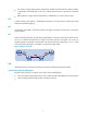
Figure 17 IGP shortcut and forwarding adjacency A TE tunnel is present between Router D and Router C. With IGP shortcut enabled, the ingress node Router D can use this tunnel when calculating IGP routes. This tunnel, however, is invisible to Router A. Therefore, Router A cannot use this tunnel to reach Router C. With forwarding adjacency enabled, Router A can know the presence of the TE tunnel and forward traffic to Router C to Router D though this tunnel.
• Standard backup where a secondary CR-LSP is created to take over after the primary CR-LSP fails. FRR FRR provides a quick per-link or per-node protection on an LSP. In this method, once a link or node fails on a path, FRR comes up to reroute the path to a new link or node to bypass the failed link or node. This can happen in as fast as 50 milliseconds, thereby minimizing data loss.
Figure 19 FRR node protection Deploying FRR When configuring the bypass LSP, make sure the protected link or node is not on the bypass LSP. As bypass LSPs are pre-established, FRR requires extra bandwidth. When network bandwidth is insufficient, use FRR for crucial interfaces or links only. DiffServ-aware TE Diff-Serv is a model that provides differentiated QoS guarantees based on class of service. MPLS TE is a traffic engineering solution that focuses on optimizing network resources allocation.
• The prestandard mode is proprietary, and therefore a device operating in prestandard mode cannot communicate with devices of some other vendors. The IETF mode is a standard mode implemented according to relative RFCs. A device operating in IETF mode can communicate with devices of other vendors. How DS-TE operates A device takes the following steps to establish MPLS TE tunnels according to CTs of traffic trunks: 1. Determines the CT of traffic flows.
• The total bandwidth occupied by CT 0, CT 1, and CT 2 cannot exceed the maximum reservable bandwidth. Figure 21 MAM bandwidth constraints model 3. Checks whether the traffic trunk matches an existing TE class. The device checks whether the CT and the LSP setup/holding priority of the traffic trunk matches an existing TE class.
To simplify the configuration, when setting up an LDP LSP across the core layer, you can use the MPLS TE tunnel that is already established in the core layer. As shown in Figure 23, when using the MPLS TE tunnel to establish the LDP LSP, you do not need to establish local LDP sessions between neighboring LSRs in the core layer. All you need to do is to establish a remote session between the ingress node and egress node of the MPLS TE tunnel.
Task Remarks MPLS TE tunnel Configuring an MPLS TE tunnel with a dynamic signaling protocol Use either method. Configuring RSVP-TE advanced features Optional. Tuning CR-LSP setup Optional. Tuning MPLS TE tunnel setup Optional. Forwarding traffic along MPLS TE tunnels using static routes Configuring traffic forwarding Forwarding traffic along MPLS TE tunnels using policy routing Required. Use any method.
Step Command Remarks ip address ip-address netmask Optional. 10. Set the tunnel protocol to MPLS TE. tunnel-protocol mpls te N/A 11. Configure the destination address of the tunnel. destination ip-address N/A 12. Configure the tunnel ID of the tunnel. mpls te tunnel-id tunnel-id N/A 13. Submit the current tunnel configuration. mpls te commit N/A 9. Assign an IP address to the tunnel interface. For information about tunnel interfaces, see Layer 3—IP Services Configuration Guide.
Creating an MPLS TE tunnel over a static CR-LSP Creating MPLS TE tunnels over static CR-LSPs does not involve configuration of tunnel constraints or the issue of IGP TE extension or CSPF. Create a static CR-LSP and a TE tunnel using static signaling and then associate them. Despite its ease of configuration, the application of MPLS TE tunnels over static CR-LSPs is restricted because they cannot dynamically adapt to network changes. Static CR-LSPs are special static LSPs.
Step 5. Return to system view. Command Remarks quit N/A • On the ingress node: static-cr-lsp ingress tunnel-name destination dest-addr { nexthop next-hop-addr | outgoing-interface interface-type interface-number } out-label out-label-value [ bandwidth [ ct0 | ct1 | ct2 | ct3 ] bandwidth-value ] • On a transit node: 6.
Task Remarks Configuring MPLS TE properties for a link Optional. Configuring CSPF Optional. Configuring OSPF TE Required when CSPF is configured. Configuring IS-IS TE Choose one depending on the IGP protocol used. Configuring an MPLS TE explicit path Optional. Configuring MPLS TE tunnel constraints Optional. Establishing an MPLS TE tunnel with CR-LDP Optional. Use either method. Establishing an MPLS TE tunnel with RSVP-TE By default, RSVP-TE is used for establishing an MPLS TE tunnel.
Configuring CSPF With CSPF enabled, a node uses CSPF to calculate the shortest path that satisfies TE requirements. To configure CSPF: Step Command Remarks 1. Enter system view. system-view N/A 2. Enter MPLS view. mpls N/A 3. Enable CSPF on your device. mpls te cspf Disabled by default. Configuring OSPF TE Configure OSPF TE if the routing protocol is OSPF and a dynamic signaling protocol is used for MPLS TE tunnel setup.
the MTU of each IS-IS enabled interface to be equal to or greater than 512 bytes to guarantee that IS-IS LSPs can be flooded on the network. IS-IS TE does not support secondary IP address advertisement. With IS-IS TE enabled on an interface configured with multiple IP addresses, IS-IS TE advertises only the primary IP address of the interface through the sub-TLV of IS reachability TLV (type 22). HP recommends that you avoid enabling IS-IS TE on an interface configured with secondary IP addresses.
Step Command Remarks Optional. 3. 4. Add a node to the explicit path. Specify a next hop IP address on the explicit path. add hop ip-address1 [ include [ loose | strict ] | exclude ] { after | before } ip-address2 next hop ip-address [ include [ loose | strict ] | exclude ] By default, the include keyword and the strict keyword apply. The explicit path traverses the specified node and the next node is a strict node. The next hop is a strict node by default.
Step Command Remarks 1. Enter system view. system-view N/A 2. Enter MPLS TE tunnel interface view. interface tunnel tunnel-number N/A 3. Set the signaling protocol for setting up MPLS TE tunnels to CR-LDP. mpls te signal-protocol crldp RSVP-TE applies by default. Submit current tunnel configuration. mpls te commit N/A 4.
Establish an MPLS TE tunnel with RSVP-TE. • Configuring RSVP reservation style Each LSP set up using RSVP-TE is assigned a resource reservation style. During an RSVP session, the receiver decides which reservation style can be used for this session and thus which LSPs can be used. The following reservation styles are available: • FF—Resources are reserved for individual senders and cannot be shared among senders on the same session.
Configuring the RSVP refresh mechanism To enhance reliability of RSVP message transmission, the Message_ID extension mechanism is used to acknowledge RSVP messages. The Message_ID extension mechanism is also referred to as "the reliability mechanism" throughout this document. After you enable RSVP message acknowledgement on an interface, you can enable retransmission. To use Srefresh, you must use the Message_ID extension.
Configuring RSVP-TE resource reservation confirmation Reservation confirmation is initiated by the receiver, which sends the Resv message with an object requesting reservation confirmation. Receiving the ResvConf message does not mean resource reservation is established. It only indicates that resources are reserved on the farthest upstream node where the Resv message arrived and the resources can be preempted. To configure RSVP-TE resource reservation confirmation: Step Command Remarks 1.
Step 3. Configure a DSCP value for outgoing RSVP packets. Command Remarks mpls rsvp-te dscp dscp-value By default, the DSCP value for outgoing RSVP packets is 48. Configuring RSVP-TE GR The RSVP-TE GR function depends on the extended hello capability of RSVP-TE. Enable the extended hello capability of RSVP-TE before configuring RSVP-TE GR. To configure RSVP-TE GR on each device to act as the GR restarter or a GR helper: Step Command Remarks 1. Enter system view. system-view N/A 2.
Tuning CR-LSP setup A CR-LSP is established through the signaling protocol based on the path calculated by CSPF using TEDB and constraints. MPLS TE can affect CSPF calculation in many ways to determine the path that a CR-LSP can traverse. The configuration tasks described in this section are about CSPF of MPLS TE. They must be used in conjunction with CSPF and the dynamic signal protocol (CR-LDP or RSVP-TE). Before performing them, be aware of each configuration objective and its impact on your system.
Step Command Remarks 1. Enter system view. system-view N/A 2. Enter MPLS TE tunnel interface view. interface tunnel tunnel-number N/A 3. Enable route pinning. mpls te route-pinning Disabled by default. 4. Submit current tunnel configuration. mpls te commit N/A. Configuring administrative group and affinity attribute The affinity attribute of an MPLS TE tunnel identifies the properties of the links that the tunnel can use.
Configuring CR-LSP reoptimization Dynamic CR-LSP optimization involves the periodic calculation of paths that traffic trunks traverse. If a better route is found for an existing CR-LSP, a new CR-LSP is established to replace the old one, and services are switched to the new CR-LSP. To configure CR-LSP reoptimization: Step Command Remarks 1. Enter system view. system-view N/A 2. Enter MPLS TE tunnel interface view. interface tunnel tunnel-number N/A 3.
Step 2. Enter MPLS TE tunnel interface view. Command Remarks interface tunnel tunnel-number N/A Use either command. 3. 4. Enable the system to record routes or labels when setting up the tunnel. Submit current tunnel configuration. • Record routes: mpls te record-route Both route recording and label recording are disabled by default. • Record routes and labels: The mpls te record-route label command is not supported when the signaling protocol is CR-LDP.
Step Command 3. Assign priorities to the tunnel. mpls te priority setup-priority [ hold-priority ] 4. Submit current tunnel configuration. mpls te commit Remarks Optional. The default setup and holding priorities are 7. N/A Configuring traffic forwarding Before you configure traffic forwarding, complete the following tasks: • Configure basic MPLS. • Configure basic MPLS TE. • Configure MPLS TE tunnels. Forwarding traffic along MPLS TE tunnels using static routes Step 1. 2.
Step Command Remarks 3. Define an ACL rule. rule [ rule-id ] { deny | permit } protocol [ destination { dest-addr dest-wildcard | any } | destination-port operator port1 [ port2 ] | dscp dscp | established | fragment | icmp-type { icmp-type icmp-code | icmp-message } | logging | precedence precedence | reflective | source { sour-addr sour-wildcard | any } | source-port operator port1 [ port2 ] | time-range time-name | tos tos | vpn-instance vpn-instance-name ] * N/A 4. Return to system view.
Step Command Remarks 1. Enter system view. system-view N/A 2. Enter MPLS TE tunnel interface view. interface tunnel tunnel-number N/A 3. Configure the IGP to take the MPLS TE tunnels in up state into account when performing enhanced SPF calculation. mpls te igp shortcut [ isis | ospf ] MPLS TE tunnels are not considered in the enhanced SPF calculation of IGP. If no IGP type is specified, the configuration applies to both OSPF and ISIS by default. Optional. 4.
Configuring traffic forwarding tuning parameters In MPLS TE, you can configure traffic forwarding tuning parameters, such as the failed link timer and flooding thresholds, to change paths that IP or MPLS traffic flows traverse or to define type of traffic that may travel down a TE tunnel. The configurations described in this section are used in conjunction with CSPF and a dynamic signaling protocol, such as RSVP-TE. Configuring the failed link timer A CSPF failed link timer starts once a link goes down.
Step Command Remarks N/A 2. Enter MPLS view. mpls 3. Specify the metric type to use when no metric type is explicitly configured for a tunnel. mpls te path metric-type { igp | te } TE metrics of links are used by default. Return to system view. quit N/A interface tunnel tunnel-number If you do not configure the mpls te path metric-type command in MPLS TE tunnel interface view, the configuration in MPLS view takes effect. 4. Optional. 5. Enter MPLS TE tunnel interface view. 6.
Configuration guidelines • The sampling interval configured in MPLS view applies to all MPLS TE tunnels. The output rates of all MPLS TE tunnels are recorded every sampling interval to calculate the actual average bandwidth of an MPLS TE tunnel in one sampling interval. • Once the mpls te auto-bandwidth adjustment frequency command you configured in MPLS TE tunnel interface view takes effect, an adjustment frequency timer starts.
Step Command Remarks Optional. 11. Reset automatic bandwidth adjustment. reset mpls te auto-bandwidth adjustment timers After this command is executed, the system clears the output rate sampling information and the remaining time to the next bandwidth adjustment to start a new output rate sampling and bandwidth adjustment. Configuring CR-LSP backup CR-LSP backup provides end-to-end path protection to protect the entire LSP.
A bypass tunnel only forwards data traffic when a protected tunnel fails. To allow a bypass tunnel to also forward data traffic when the protected tunnels are normal, you must make sure that the bypass tunnel has adequate bandwidth. A bypass tunnel cannot be used for services like VPN. NOTE: • The FRR feature is not supported when the signaling protocol is CR-LDP. • Do not configure both FRR and RSVP authentication on the same interface.
Step Command Remarks 1. Enter system view. system-view N/A 2. Enter interface view of the bypass tunnel. interface tunnel tunnel-number N/A • For node protection, this is the 3. Specify the destination address of the bypass tunnel. destination ip-address LSR ID of the next hop router of PLR. • For link protection, this is the LSR ID of the next hop device of PLR. Bandwidth is not protected by default. 4. Configure the bandwidth and the type of LSPs that the bypass tunnel can protect.
NOTE: RSVP hello extension is configured to detect node failures caused by problems such as signaling error other than failures caused by link failures. Configuring the FRR polling timer The protection provided by FRR is temporary. Once a protected LSP becomes available again or a new LSP is established, traffic is switched to the protected or new LSP.
Configuring MPLS LSP tracert MPLS LSP tracert can be used to locate errors of an MPLS TE tunnel. It sends MPLS echo requests to the nodes along the MPLS TE tunnel to be inspected, with the TTL increasing from 1 to a specific value. Each node along the MPLS TE tunnel returns an MPLS echo reply to the ingress due to TTL timeout. Thus, the ingress can collect information about each hop along the MPLS TE tunnel, so as to locate the failed node.
• If you enable both FRR and BFD for an MPLS TE tunnel, to make sure the BFD session is not down during an FRR switching, give the BFD detection interval a greater value than the FRR detection interval. • In a BFD session for detecting an MPLS TE tunnel's connectivity, the ingress node always operates in active mode and the egress node always operates in passive mode. The bfd session init-mode command does not take effect on the ingress and egress nodes of such a BFD session.
After you configure periodic LSP tracert and the mpls te failure-action teardown command for an MPLS TE tunnel, once an RSVP-TE tunnel failure occurs, the periodic LSP tracert function can detect the failure, and if RSVP does not reestablish the RSVP-TE tunnel within a specific period of time, MPLS TE removes the failed RSVP-TE tunnel and then reestablishes it. To configure periodic LSP tracert for an MPLS TE tunnel: Step 1. Enter system view.
Task Command Remarks Display information about explicit paths. display explicit-path [ path-name ] [ | { begin | exclude | include } regular-expression ] Available in any view. Display information about static CR-LSPs. display mpls static-cr-lsp [ lsp-name lsp-name ] [ egress | ingress | transit ] [ { include | exclude } ip-address prefix-length ] [ verbose ] [ | { begin | exclude | include } regular-expression ] Available in any view. Display RSVP-TE configuration.
Task Command Remarks Display statistics about RSVP-TE. display mpls rsvp-te statistics { global | interface [ interface-type interface-number ] } [ | { begin | exclude | include } regular-expression ] Available in any view. Display criteria-compliant information about CSPF-based TEDB. display mpls te cspf tedb { all | area area-id | interface ip-address | network-lsa | node [ mpls-lsr-id ] } [ | { begin | exclude | include } regular-expression ] Available in any view.
Task Command Remarks Display information about OSPF TE. display ospf [ process-id ] mpls-te [ area area-id ] [ self-originated ] [ | { begin | exclude | include } regular-expression ] Available in any view. Display the latest TE information advertised by IS-IS TE. display isis traffic-eng advertisements [ [ level-1 | level-1-2 | level-2 ] | [ lsp-id lsp-id | local ] ] * [ process-id | vpn-instance vpn-instance-name ] [ | { begin | exclude | include } regular-expression ] Available in any view.
MPLS TE configuration examples MPLS TE using static CR-LSP configuration example Network requirements Router A, Router B, and Router C run IS-IS. Establish a TE tunnel using a static CR-LSP between Router A and Router C. Figure 24 Network diagram Configuration procedure 1. Configure IP addresses and masks for the interfaces according to Figure 24. (Details not shown.) 2. Enable IS-IS to advertise host routes with LSR IDs as destinations: # Configure Router A.
[RouterB] interface giabitethernet 2/1/2 [RouterB-GigabitEthernet2/1/2] isis enable 1 [RouterB-GigabitEthernet2/1/2] quit [RouterB] interface loopback 0 [RouterB-LoopBack0] isis enable 1 [RouterB-LoopBack0] quit # Configure Router C. system-view [RouterC] isis 1 [RouterC-isis-1] network-entity 00.0005.0000.0000.0003.
[RouterB] interface giabitethernet 2/1/1 [RouterB-GigabitEthernet2/1/1] mpls [RouterB-GigabitEthernet2/1/1] mpls te [RouterB-GigabitEthernet2/1/1] quit [RouterB] interface giabitethernet 2/1/2 [RouterB-GigabitEthernet2/1/2] mpls [RouterB-GigabitEthernet2/1/2] mpls te [RouterB-GigabitEthernet2/1/2] quit # Configure Router C. [RouterC] mpls lsr-id 3.3.3.
Tunnel source unknown, destination 3.3.3.
Name FEC I/O Label I/O If Tunnel0 -/- 20/30 GE2/1/1/GE2/1/2 State Up [RouterC] display mpls static-cr-lsp total statics-cr-lsp : 1 Name FEC I/O Label I/O If Tunnel0 -/- 30/NULL GE2/1/1/- State Up On an MPLS TE tunnel configured using a static CR-LSP, traffic is forwarded directly based on label at the transit nodes and egress node. Therefore, it is normal that the FEC field in the sample output is empty on Router B and Router C. 7.
[RouterA] isis 1 [RouterA-isis-1] network-entity 00.0005.0000.0000.0001.00 [RouterA-isis-1] quit [RouterA] interface giabitethernet 2/1/1 [RouterA-GigabitEthernet2/1/1] isis enable 1 [RouterA-GigabitEthernet2/1/1] isis circuit-level level-2 [RouterA-GigabitEthernet2/1/1] quit [RouterA] interface loopback 0 [RouterA-LoopBack0] isis enable 1 [RouterA-LoopBack0] isis circuit-level level-2 [RouterA-LoopBack0] quit # Configure Router B. system-view [RouterB] isis 1 [RouterB-isis-1] network-entity 00.
[RouterD-isis-1] network-entity 00.0005.0000.0000.0004.00 [RouterD-isis-1] quit [RouterD] interface giabitethernet 2/1/1 [RouterD-GigabitEthernet2/1/1] isis enable 1 [RouterD-GigabitEthernet2/1/1] isis circuit-level level-2 [RouterD-GigabitEthernet2/1/1] quit [RouterD] interface loopback 0 [RouterD-LoopBack0] isis enable 1 [RouterD-LoopBack0] isis circuit-level level-2 [RouterD-LoopBack0] quit Execute the display ip routing-table command on each router.
[RouterB-GigabitEthernet2/1/1] mpls [RouterB-GigabitEthernet2/1/1] mpls te [RouterB-GigabitEthernet2/1/1] mpls rsvp-te [RouterB-GigabitEthernet2/1/1] quit [RouterB] interface pos 5/1/0 [RouterB-POS5/1/0] mpls [RouterB-POS5/1/0] mpls te [RouterB-POS5/1/0] mpls rsvp-te [RouterB-POS5/1/0] quit # Configure Router C. [RouterC] mpls lsr-id 3.3.3.
[RouterB-isis-1] traffic-eng level-2 [RouterB-isis-1] quit # Configure Router C. [RouterC] isis 1 [RouterC-isis-1] cost-style wide [RouterC-isis-1] traffic-eng level-2 [RouterC-isis-1] quit # Configure Router D. [RouterD] isis 1 [RouterD-isis-1] cost-style wide [RouterD-isis-1] traffic-eng level-2 [RouterD-isis-1] quit 5. Configure MPLS TE attributes of links: # Configure maximum link bandwidth and maximum reservable bandwidth on Router A.
[RouterA-Tunnel1] destination 4.4.4.9 [RouterA-Tunnel1] mpls te tunnel-id 10 [RouterA-Tunnel1] mpls te signal-protocol rsvp-te [RouterA-Tunnel1] mpls te bandwidth 2000 [RouterA-Tunnel1] mpls te commit [RouterA-Tunnel1] quit 7. Verify the configuration: Execute the display interface tunnel command on Router A. You can see that the tunnel interface is up.
BackUpBW Type : - Route Pinning : Disabled BackUpBW : Retry Limit : 10 Retry Interval: Reopt : Disabled Reopt Freq Back Up Type : None Back Up LSPID : - Auto BW : Min BW : Current Collected BW: - Interfaces Protected: - VPN Bind Type : NONE VPN Bind Value : - Car Policy : Disabled Tunnel Group : Primary Primary Tunnel : - Backup Tunnel : - Group Status : - - 10 sec : - Disabled Auto BW Freq : - - Max BW - : Execute the display mpls te cspf tedb a
Figure 26 Network diagram Device Router A Router B Interface IP address Device Router C Interface IP address Loop0 1.1.1.9/32 Loop0 3.3.3.9/32 GE2/1/1 10.1.1.1/24 GE2/1/1 30.1.1.1/24 Loop0 2.2.2.9/32 POS5/1/0 20.1.1.2/24 Loop0 4.4.4.9/32 GE2/1/1 30.1.1.2/24 GE2/1/1 10.1.1.2/24 POS5/1/0 20.1.1.1/24 Router D Configuration procedure 1. Configure IP addresses and masks for the interfaces according to Figure 26. (Details not shown.) 2.
[RouterC-ospf-1] area 0 [RouterC-ospf-1-area-0.0.0.0] network 30.1.1.0 0.0.0.255 [RouterC-ospf-1-area-0.0.0.0] network 3.3.3.9 0.0.0.0 [RouterC-ospf-1-area-0.0.0.0] quit [RouterC-ospf-1] quit # Configure OSPF on Router D. system-view [RouterD] ospf [RouterD-ospf-1] area 0 [RouterD-ospf-1-area-0.0.0.0] network 30.1.1.0 0.0.0.255 [RouterD-ospf-1-area-0.0.0.0] network 4.4.4.9 0.0.0.0 [RouterD-ospf-1-area-0.0.0.
Destinations : 10 4. Destination/Mask Proto 1.1.1.9/32 2.2.2.9/32 Routes : 10 Pre Cost NextHop Interface Direct 0 0 127.0.0.1 InLoop0 OSPF 10 1 10.1.1.2 GE2/1/1 3.3.3.9/32 O_ASE 150 1 10.1.1.2 GE2/1/1 4.4.4.9/32 O_ASE 150 1 10.1.1.2 GE2/1/1 10.1.1.0/24 Direct 0 0 10.1.1.1 GE2/1/1 10.1.1.1/32 Direct 0 0 127.0.0.1 InLoop0 20.1.1.0/24 O_ASE 150 1 10.1.1.2 GE2/1/1 30.1.1.0/24 O_ASE 150 1 10.1.1.2 GE2/1/1 127.0.0.0/8 Direct 0 0 127.0.0.1 InLoop0 127.0.0.
[RouterC-mpls] mpls rsvp-te [RouterC-mpls] mpls te cspf [RouterC-mpls] quit [RouterC] interface giabitethernet 2/1/1 [RouterC-GigabitEthernet2/1/1] mpls [RouterC-GigabitEthernet2/1/1] mpls te [RouterC-GigabitEthernet2/1/1] mpls rsvp-te [RouterC-GigabitEthernet2/1/1] quit [RouterC] interface pos 5/1/0 [RouterC-POS5/1/0] mpls [RouterC-POS5/1/0] mpls te [RouterC-POS5/1/0] mpls rsvp-te [RouterC-POS5/1/0] quit # Configure Router D. [RouterD] mpls lsr-id 4.4.4.
# Configure Router D. [RouterD] ospf [RouterD-ospf-1] opaque-capability enable [RouterD-ospf-1] area 0 [RouterD-ospf-1-area-0.0.0.0] mpls-te enable [RouterD-ospf-1-area-0.0.0.0] quit [RouterD-ospf-1] quit 6. Configure a loose explicit route: # Configure a loose explicit route on Router A. [RouterA] explicit-path atod enable [RouterA-explicit-path-atod] next hop 10.1.1.2 include loose [RouterA-explicit-path-atod] next hop 20.1.1.2 include loose [RouterA-explicit-path-atod] next hop 30.1.1.
[RouterA-Tunnel1] ip address 7.1.1.1 255.255.255.0 [RouterA-Tunnel1] tunnel-protocol mpls te [RouterA-Tunnel1] destination 4.4.4.9 [RouterA-Tunnel1] mpls te tunnel-id 10 [RouterA-Tunnel1] mpls te signal-protocol rsvp-te [RouterA-Tunnel1] mpls te bandwidth 2000 [RouterA-Tunnel1] mpls te path explicit-path atod preference 5 [RouterA-Tunnel1] mpls te commit [RouterA-Tunnel1] quit 9. Verify the configuration: Execute the display interface tunnel command on Router A.
Explicit Path Name : atod Tie-Breaking Policy : None Metric Type : None Loop Detection : Disabled Record Route : Disabled Record Label : Disabled FRR Flag : Disabled BackUpBW Flag: Not Supported BackUpBW Type : - BackUpBW - Route Pinning : Disabled Retry Limit : 10 Retry Interval: Reopt : Disabled Reopt Freq Back Up Type : None Back Up LSPID : - Auto BW : Min BW : Current Collected BW: - Interfaces Protected: - VPN Bind Type : NONE VPN Bind Value : -
10.1.1.1/32 Direct 0 0 127.0.0.1 InLoop0 20.1.1.0/24 O_ASE 1 10.1.1.2 GE2/1/1 30.1.1.0/24 Static 1 0 7.1.1.1 Tun1 127.0.0.0/8 Direct 0 0 127.0.0.1 InLoop0 127.0.0.1/32 Direct 0 0 127.0.0.1 InLoop0 150 RSVP-TE GR configuration example Network requirements Router A, Router B and Router C are running IS-IS. All of them are Level-2 devices and support RSVP hello extension. Use RSVP-TE to create a TE tunnel from Router A to Router C.
[RouterB-mpls] mpls rsvp-te hello [RouterB-mpls] interface giabitethernet 2/1/1 [RouterB-GigabitEthernet2/1/1] mpls [RouterB-GigabitEthernet2/1/1] mpls te [RouterB-GigabitEthernet2/1/1] mpls rsvp-te [RouterB-GigabitEthernet2/1/1] mpls rsvp-te hello [RouterB-GigabitEthernet2/1/1] quit [RouterB] interface giabitethernet 2/1/2 [RouterB-GigabitEthernet2/1/2] mpls [RouterB-GigabitEthernet2/1/2] mpls te [RouterB-GigabitEthernet2/1/2] mpls rsvp-te [RouterB-GigabitEthernet2/1/2] mpls rsvp-te hello [RouterB-GigabitE
Neighbor Addr: 10.1.1.2 SrcInstance: 880 NbrSrcInstance: 5017 PSB Count: 0 RSB Count: 1 Hello Type Sent: REQ Neighbor Hello Extension: ENABLE SRefresh Enable: NO Graceful Restart State: Ready Restart Time: 120 Sec Recovery Time: 300 Sec MPLS RSVP-TE and BFD cooperation configuration example Network requirements Run OSPF on Router A and Router B to ensure IP connectivity. Enable MPLS RSVP-TE BFD on the interfaces connecting the two routers.
[RouterB-GigabitEthernet2/1/1] mpls te [RouterB-GigabitEthernet2/1/1] mpls rsvp-te [RouterB-GigabitEthernet2/1/1] mpls rsvp-te bfd enable [RouterB-GigabitEthernet2/1/1] quit 2. Configure OSPF: # Configure Router A. system-view [RouterA] ospf [Router-A-ospf-1] area 0 [Router-A-ospf-1-area-0.0.0.0] network 12.12.12.1 0.0.0.255 [Router-A-ospf-1-area-0.0.0.0] network 1.1.1.1 0.0.0.0 [Router-A-ospf-1-area-0.0.0.0] quit [Router-A-ospf-1] quit # Configure Router B.
Local Discr: 19 Remote Discr: 18 Source IP: 12.12.12.1 Destination IP: 12.12.12.2 Session State: Up Interface: GigabitEthernet2/1/1 Min Trans Inter: 400ms Act Trans Inter: 400ms Min Recv Inter: 400ms Act Detect Inter: 2000ms Running Up for: 00:00:01 Auth mode: None Connect Type: Direct Board Num: 6 Protocol: RSVP Diag Info: No Diagnostic MPLS TE using CR-LDP configuration example Network requirements Router A, Router B, Router C and Router D are running OSPF and all of them are in area 0.
[RouterA] mpls lsr-id 1.1.1.9 [RouterA] mpls [RouterA-mpls] mpls te [RouterA-mpls] mpls te cspf [RouterA-mpls] quit [RouterA] interface giabitethernet 2/1/1 [RouterA-GigabitEthernet2/1/1] mpls [RouterA-GigabitEthernet2/1/1] mpls te [RouterA-GigabitEthernet2/1/1] quit # Configure Router B. [RouterB] mpls lsr-id 2.2.2.
# Configure Router A. [RouterA] ospf [RouterA-ospf-1] opaque-capability enable [RouterA-ospf-1] area 0 [RouterA-ospf-1-area-0.0.0.0] mpls-te enable [RouterA-ospf-1-area-0.0.0.0] quit [RouterA-ospf-1] quit # Configure Router B. [RouterB] ospf [RouterB-ospf-1] opaque-capability enable [RouterB-ospf-1] area 0 [RouterB-ospf-1-area-0.0.0.0] mpls-te enable [RouterB-ospf-1-area-0.0.0.0] quit [RouterB-ospf-1] quit # Configure Router C.
[RouterC-GigabitEthernet2/1/1] quit [RouterC] interface giabitethernet 2/1/2 [RouterC-GigabitEthernet2/1/2] mpls te max-link-bandwidth 10000 [RouterC-GigabitEthernet2/1/2] mpls te max-reservable-bandwidth 5000 [RouterC-GigabitEthernet2/1/2] quit # Configure maximum link bandwidth and maximum reservable bandwidth on Router D.
[RouterD-mpls-ldp] quit [RouterD] interface giabitethernet 2/1/1 [RouterD-GigabitEthernet2/1/1] mpls ldp [RouterD-GigabitEthernet2/1/1] quit Execute the display mpls ldp session command on each router. You can see that an LDP session has been established and its state is operational.
Tunnel Name : Tunnel2 Tunnel Desc : Tunnel2 Interface Tunnel State Desc : CR-LSP is Up Tunnel Attributes : LSP ID : Session ID : 1.1.1.9:2 Admin State : UP Oper State Ingress LSR ID : 1.1.1.9 Egress LSR ID: 4.4.4.
-----------------------------------------------LSA Type : Opq-Area Opaque Type : 1 Opaque ID : 1 Advertising Router ID : 1.1.1.9 LSA : 811 Age Length : 200 LSA : E O Options LS Seq Number : 8000000D CheckSum : B1C4 Link Type : MultiAccess Link ID : 10.1.1.2 Local Interface Address : 10.1.1.1 Remote Interface Address : 0.0.0.
8. Opaque Type : 1 Opaque ID : 0 Advertising Router ID : 1.1.1.9 LSA : 1118 Age Length : 28 LSA : E O Options LS Seq Number : 8000000B CheckSum : ECBF MPLS TE Router ID : 1.1.1.9 Create a static route to direct traffic to the MPLS TE tunnel: [RouterA] ip route-static 30.1.1.2 24 tunnel 2 preference 1 Execute the display ip routing-table command on Router A. You can see a static route entry with Tunnel2 as the outgoing interface.
Execute the display ip routing-table command on each router. You can see that all nodes have learned the host routes of other nodes with LSR IDs as destinations. 3. Configure basic MPLS TE, and enable RSVP-TE and CSPF: system-view [RouterA] mpls lsr-id 1.1.1.
Last 300 seconds output: 0 packets input, 0 bytes/sec, 0 packets/sec 0 bytes 0 input error 0 packets output, 0 bytes 0 output error 5. Verify the configuration: # Execute the display mpls te tunnel command on Router A. You can see that two tunnels are present with the outgoing interface being GigabitEthernet 2/1/1 and POS 5/1 respectively. This indicates that a backup CR-LSP was created upon creation of the primary CR-LSP. [RouterA] display mpls te tunnel LSP-Id Destination In/Out-If Name 1.1.1.
2 40.1.1.2 50 ms 50 ms 49 ms # Execute the display mpls te tunnel command on Router A. You can see that only the tunnel traversing Router D is present: [RouterA] display mpls te tunnel LSP-Id Destination In/Out-If Name 1.1.1.9:2054 3.3.3.9 -/POS5/1/1 Tunnel3 Configuring ordinary CR-LSP backup is almost the same as configuring hot CR-LSP backup except that you need to replace the mpls te backup hot-standby command with the mpls te backup ordinary command.
GE 2/1/1 4.1.1.2/24 Configuration procedure 1. Configure IP addresses and masks for the interfaces according to Figure 31. (Details not shown.) 2. Configure the IGP protocol: # Enable IS-IS to advertise host routes with LSR IDs as destinations on each node. (Details not shown.) # Execute the display ip routing-table command on each router. You can see that all nodes have learned the host routes of other nodes with LSR IDs as destinations.
[RouterB-mpls] mpls te cspf [RouterB-mpls] quit [RouterB] interface giabitethernet 2/1/1 [RouterB-GigabitEthernet2/1/1] mpls [RouterB-GigabitEthernet2/1/1] mpls te [RouterB-GigabitEthernet2/1/1] mpls rsvp-te [RouterB-GigabitEthernet2/1/1] quit [RouterB] interface giabitethernet 2/1/2 [RouterB-GigabitEthernet2/1/2] mpls [RouterB-GigabitEthernet2/1/2] mpls te [RouterB-GigabitEthernet2/1/2] mpls rsvp-te [RouterB-GigabitEthernet2/1/2] quit [RouterB] interface pos 5/1/0 [RouterB-POS5/1/0] mpls [RouterB-POS5/1/0]
Output queue : (Urgent queuing : Size/Length/Discards) 0/100/0 Output queue : (Protocol queuing : Size/Length/Discards) Output queue : (FIFO queuing : Size/Length/Discards) Last 300 seconds input: 0/75/0 0 bytes/sec, 0 packets/sec Last 300 seconds output: 0 packets input, 0/500/0 0 bytes/sec, 0 packets/sec 0 bytes 0 input error 0 packets output, 0 bytes 0 output error Execute the display mpls te tunnel-interface command on Router A to view the configuration of the tunnel interface.
# Create an explicit path for the bypass LSP. [RouterB] explicit-path by-path [RouterB-explicit-path-by-path] next hop 3.2.1.2 [RouterB-explicit-path-by-path] next hop 3.3.1.2 [RouterB-explicit-path-by-path] next hop 3.3.3.3 [RouterB-explicit-path-by-path] quit # Create the bypass tunnel. [RouterB] interface tunnel 5 [RouterB-Tunnel5] ip address 11.1.1.1 255.255.255.0 [RouterB-Tunnel5] tunnel-protocol mpls te [RouterB-Tunnel5] destination 3.3.3.
-----------------------------------------------------------------FEC In/Out Label In/Out IF 4.4.4.4/32 3/NULL GE2/1/1/- Vrf Name [RouterE] display mpls lsp -----------------------------------------------------------------LSP Information: RSVP LSP -----------------------------------------------------------------FEC In/Out Label In/Out IF 3.3.3.3/32 1024/3 POS5/1/0/POS5/1 Vrf Name Execute the display mpls te tunnel command on each router.
6. BypassTunnel : Tunnel Index[Tunnel5], InnerLabel[1024] Mpls-Mtu : 1500 No : 2 IngressLsrID : 2.2.2.2 LocalLspID : 1 Tunnel-Interface : Tunnel5 Fec : 3.3.3.3/32 Nexthop : 3.2.1.
BackUpBW Type : - Route Pinning : Disabled BackUpBW : Retry Limit : 10 Retry Interval: Reopt : Disabled Reopt Freq Back Up Type : None Back Up LSPID : - Auto BW : Disabled Auto BW Freq : - Min BW : - Max BW - Current Collected BW: - Interfaces Protected: - VPN Bind Type : NONE VPN Bind Value : - Car Policy : Disabled Tunnel Group : Primary Primary Tunnel : - Backup Tunnel : - Group Status : - Tunnel Name : Tunnel4 Tunnel Desc : Tunnel4 Interface
Car Policy : Disabled Tunnel Group : Primary Primary Tunnel : - Backup Tunnel : - Group Status : - If you execute the display mpls te tunnel-interface command immediately after an FRR protection switch, you are likely to see two CR-LSPs in up state are present. This is normal because the make-before-break mechanism of FRR introduces a delay before removing the old LSP after a new LSP is created. # Execute the display mpls lsp verbose command on Router B.
# Set the FRR polling timer to 5 seconds on PLR. [RouterB] mpls [RouterB-mpls] mpls te timer fast-reroute 5 [RouterB-mpls] quit # Bring the protected outgoing interface up on PLR. [RouterB] interface giabitethernet 2/1/2 [RouterB-GigabitEthernet2/1/2] undo shutdown %Sep 7 09:01:31 2004 RouterB IFNET/5/UPDOWN:Line protocol on the interface GigabitEthernet2/1/2 turns into UP state # Execute the display interface tunnel 4 command on Router A to identify the state of the primary LSP.
Configuration procedure 1. Configure IP addresses for the interfaces according to Figure 32. (Details not shown.) 2. Configure IS-IS, and advertise host routes with LSR IDs as destinations: # Configurations on Router A. system-view [RouterA] isis 1 [RouterA-isis-1] network-entity 00.0005.0000.0000.0001.
[RouterC-LoopBack0] isis enable 1 [RouterC-LoopBack0] isis circuit-level level-2 [RouterC-LoopBack0] quit # Configurations on Router D. system-view [RouterD] isis 1 [RouterD-isis-1] network-entity 00.0005.0000.0000.0004.
[RouterB] mpls lsr-id 2.2.2.
4. Enable IS-IS TE, and configure IS-IS to receive and send only packets whose cost style is wide: # Configure Router A. [RouterA] isis 1 [RouterA-isis-1] cost-style wide [RouterA-isis-1] traffic-eng level-2 [RouterA-isis-1] quit # Configure Router B. [RouterB] isis 1 [RouterB-isis-1] cost-style wide [RouterB-isis-1] traffic-eng level-2 [RouterB-isis-1] quit # Configure Router C.
[RouterC-POS5/1/0] mpls te max-reservable-bandwidth rdm 10000 bc1 8000 bc2 5000 bc3 2000 [RouterC-POS5/1/0] quit # Configure the maximum bandwidth and bandwidth constraints on Router D. [RouterD] interface giabitethernet 2/1/1 [RouterD-GigabitEthernet2/1/1] mpls te max-link-bandwidth 10000 [RouterD-GigabitEthernet2/1/1] mpls te max-reservable-bandwidth rdm 10000 bc1 8000 bc2 5000 bc3 2000 [RouterD-GigabitEthernet2/1/1] quit 6. Create an MPLS TE tunnel: # Create an MPLS TE tunnel on Router A.
Tunnel Attributes : LSP ID : 1.1.1.9:3 Session ID : 10 Admin State : UP Oper State Ingress LSR ID : 1.1.1.9 Egress LSR ID: 4.4.4.
8.
Figure 33 Network diagram Device Router A Router B Router D Interface IP address Device Router E Loop0 1.1.1.1/32 GE2/1/1 2.1.1.1/24 Loop0 2.2.2.2/32 GE2/1/1 2.1.1.2/24 GE2/1/2 3.1.1.1/24 Router C Interface IP address Loop0 5.5.5.5/32 POS5/1/0 3.2.1.2/24 POS5/1/1 3.3.1.1/24 Loop0 3.3.3.3/32 GE2/1/1 4.1.1.1/24 POS5/1/0 3.2.1.1/24 GE2/1/2 3.1.1.2/24 Loop0 4.4.4.4/32 POS5/1/1 3.3.1.2/24 GE2/1/1 4.1.1.2/24 Configuration procedure 1.
[RouterE] mpls [RouterE-mpls] mpls te [RouterE-mpls] mpls rsvp-te [RouterE-mpls] mpls te cspf [RouterE-mpls] quit [RouterE] interface pos 5/1/0 [RouterE-POS5/1/0] mpls [RouterE-POS5/1/0] mpls te [RouterE-POS5/1/0] mpls rsvp-te [RouterE-POS5/1/0] quit [RouterE] interface pos 5/1/1 [RouterE-POS5/1/1] mpls [RouterE-POS5/1/1] mpls te [RouterE-POS5/1/1] mpls rsvp-te [RouterE-POS5/1/1] quit # Configure Router C. system-view [RouterC] mpls lsr-id 3.3.3.
# Configure OSPF TE. [RouterB] ospf [RouterB-ospf-1] opaque-capability enable [RouterB-ospf-1] enable traffic-adjustment [RouterB-ospf-1] area 0.0.0.0 [RouterB-ospf-1-area-0.0.0.0] mpls-te enable [RouterB-ospf-1-area-0.0.0.0] quit [RouterB-ospf-1] quit After the configuration, execute the display interface tunnel command on Router B. The output shows that tunnel interface Tunnel 4 is up.
# Configure Router B. [RouterB] mpls [RouterB-mpls] mpls ldp [RouterB-mpls] quit [RouterB] interface giabitethernet 2/1/1 [RouterB-GigabitEthernet2/1/1] mpls [RouterB-GigabitEthernet2/1/1] mpls ldp [RouterB-GigabitEthernet2/1/1] quit [RouterB] mpls ldp remote-peer C [RouterB-mpls-ldp-remote-c] remote-ip 3.3.3.3 [RouterB-mpls-ldp-remote-c] quit # Configure Router C.
Session State Session Role : Passive Session FT Flag : Off : Operational MD5 Flag : Off Reconnect Timer : --- Recovery Timer : --- Negotiated Keepalive Timer : 45 Sec Keepalive Message Sent/Rcvd : 411/411 (Message Count) Label Advertisement Mode : Downstream Unsolicited Label Resource Status(Peer/Local) : Available/Available Peer Discovery Mechanism : Extended Session existed time : 000:01:42 LDP Extended Discovery Source : Remote peer: 1 (DDD:HH:MM) Addresses received from peer: (Coun
Out-Interface : POS5/1/0 LspIndex : 3073 Tunnel ID : 0x11000c LsrType : Ingress Bypass In Use : Not Exists BypassTunnel : Tunnel Index[---] ---------------------------------------------------------------------LSP Information: LDP LSP ---------------------------------------------------------------------No : VrfIndex : 2 Fec : 3.3.3.3/32 Nexthop : 10.1.1.
Figure 34 Network diagram Configuration procedure 1. Configure OSPF, making sure that PE 1 and PE 2 can learn routes from each other: # Configure PE 1. system-view [PE1] interface loopback 0 [PE1-LoopBack0] ip address 2.2.2.2 255.255.255.255 [PE1-LoopBack0] quit [PE1] interface pos 5/1/1 [PE1-POS5/1/1] ip address 10.0.0.1 255.255.255.0 [PE1-POS5/1/1] quit [PE1] ospf [PE1-ospf-1] area 0 [PE1-ospf-1-area-0.0.0.0] network 10.0.0.0 0.0.0.255 [PE1-ospf-1-area-0.0.0.0] network 2.2.2.2 0.0.0.
display ip routing-table command. You can see that the PEs have learned the routes to the loopback interfaces of each other. Take PE 1 for example: [PE1] display ospf peer verbose OSPF Process 1 with Router ID 2.2.2.2 Neighbors Area 0.0.0.0 interface 10.0.0.1(POS5/1/1)'s neighbors Router ID: 3.3.3.3 State: Full DR: None Address: 10.0.0.
[PE2-POS5/1/1] mpls rsvp-te [PE2-POS5/1/1] quit 3. Enable OSPF TE: # Configure PE 1. [PE1] ospf [PE1-ospf-1] opaque-capability enable [PE1-ospf-1] area 0 [PE1-ospf-1-area-0.0.0.0] mpls-te enable [PE1-ospf-1-area-0.0.0.0] quit [PE1-ospf-1] quit # Configure PE 2. [PE2] ospf [PE2-ospf-1] opaque-capability enable [PE2-ospf-1] area 0 [PE2-ospf-1-area-0.0.0.0] mpls-te enable [PE2-ospf-1-area-0.0.0.0] quit [PE2-ospf-1] quit 4.
[PE1-GigabitEthernet2/1/1] ip binding vpn-instance vpn1 [PE1-GigabitEthernet2/1/1] ip address 192.168.1.1 255.255.255.0 [PE1-GigabitEthernet2/1/1] quit # Configure on CE 2. system-view [CE2] interface giabitethernet 2/1/1 [CE2-GigabitEthernet2/1/1] ip address 192.168.2.2 255.255.255.0 [CE2-GigabitEthernet2/1/1] quit # Configure the VPN instance on PE 2, and bind it with the interface connected to CE 2.
# Configure PE 1 to establish the EBGP peer relationship with CE 1, and the IBGP peer relationship with PE 2. [PE1] bgp 100 [PE1-bgp] ipv4-family vpn-instance vpn1 [PE1-bgp-vpn1] peer 192.168.1.2 as-number 65001 [PE1-bgp-vpn1] import-route direct [PE1-bgp-vpn1] quit [PE1-bgp] peer 3.3.3.3 as-number 100 [PE1-bgp] peer 3.3.3.3 connect-interface loopback 0 [PE1-bgp] ipv4-family vpnv4 [PE1-bgp-af-vpnv4] peer 3.3.3.3 enable [PE1-bgp-af-vpnv4] quit [PE1-bgp] quit # Configure CE 2.
Reply from 192.168.2.2: bytes=56 Sequence=1 ttl=253 time=61 ms Reply from 192.168.2.2: bytes=56 Sequence=2 ttl=253 time=54 ms Reply from 192.168.2.2: bytes=56 Sequence=3 ttl=253 time=53 ms Reply from 192.168.2.2: bytes=56 Sequence=4 ttl=253 time=57 ms Reply from 192.168.2.2: bytes=56 Sequence=5 ttl=253 time=36 ms --- 192.168.2.2 ping statistics --5 packet(s) transmitted 5 packet(s) received 0.00% packet loss round-trip min/avg/max = 36/52/61 ms [CE2] ping 192.168.1.2 PING 192.168.1.
-----------------------------------------------------------------No : 2 VrfIndex : vpn1 Fec : 192.168.1.0/24 Nexthop : 192.168.1.
Line protocol current state: UP Description: Tunnel1 Interface The Maximum Transmit Unit is 1500 Internet Address is 12.1.1.1/24 Primary Encapsulation is TUNNEL, service-loopback-group ID not set Tunnel source unknown, destination 3.3.3.
Configuring MPLS L2VPN Overview MPLS L2VPN is an MPLS-based Layer 2 VPN technology. It uses MPLS to establish Layer 2 connections between network nodes. Using MPLS L2VPN, carriers can transparently transport Layer 2 data of different data link layer protocols (including ATM, FR, VLAN, Ethernet, and PPP) over a single MPLS or IP backbone. From the perspective of users, the MPLS or IP backbone network is a Layer 2 switched network.
MPLS L2VPN network models MPLS L2VPN network models include remote connection model and local connection model. Remote connection model As shown in Figure 35, this model connects two Layer 2 customer networks over an MPLS or IP backbone. Figure 35 Remote connection Local connection model As shown in Figure 36, this model connects two Layer 2 customer networks to the same PE. The customer networks exchange packets with each other through the PE. The PE functions like a Layer 2 switch.
To set up a VC, the two PEs assign VC labels to each other to set up a pair of unidirectional LSPs in opposite directions. By VC setup mode, MPLS L2VPN can be implemented in Circuit Cross Connect (CCC) mode, Static Virtual Circuit (SVC) mode, Martini mode, or Kompella mode. For more information, see "Implementation of MPLS L2VPN." 3. Set up ACs and bind the ACs to the VC, so the PEs can forward user packets from ACs through the VC: a.
This packet forwarding process is not applicable to the CCC mode of MPLS L2VPN. For more information about the CCC mode of MPLS L2VPN, see "CCC MPLS L2VPN." Local connection operation Local connection establishment To set up a local MPLS L2VPN connection between two CEs: 1. Set up ACs: Configure the link layer protocol on the PE and a connected CE to set up a link layer connection (such as a PPP connection) between the PE and the CE. 2.
Figure 39 CCC MPLS L2VPN network diagram After you complete the configurations as shown in Figure 39, a static LSP from PE 1 to PE 2 and a static LSP from PE 2 to PE 1 are established. Bind the two LSPs to Interface A on PE 1 and to Interface B on PE 2. A CCC connection is successfully established. The following describes how a packet is forwarded from CE 1 to CE 2: 1.
Figure 40 Label distribution in Martini mode Kompella MPLS L2VPN Kompella MPLS L2VPN employs two levels of labels to transfer user packets, and uses BGP as the signaling protocol to distribute the inner VC label. Different from other MPLS L2VPN modes, Kompella introduces the concept of VPN. It allows CEs in the same VPN to establish a connection. CEs in different VPNs cannot establish a connection. Kompella MPLS L2VPN has the following basic concepts: • CE ID—Kompella numbers CEs inside a VPN.
• Label-block Offset—Offset of the label block. When CEs increase in a VPN and the existing label block size is not enough, you do not need to withdraw the label block on the PEs. Instead, you can assign a new label block in addition to the existing label block to enlarge the label range. A PE uses LO to identify a label block among all label blocks, and to determine from which label block it assigns labels. The LO value of a label block is the sum of LRs of all previously assigned label blocks.
A PE adds the VC label assigned by the peer PE into a Layer 2 packet from a local CE. For example, when PE 1 forwards packets from CE 1 to CE 2, it adds VC label 3001. Figure 42 Label distribution in Kompella mode As shown in Figure 42, CE 1 and CE 2 belong to VPN 1. CE 3 and CE 4 belong to VPN 2. Configure route targets for the two VPNs to make sure CEs in the same VPN can set up a VC and CEs in different VPNs cannot. A VC is set up as follows (take the VC between CE 1 and CE 2 as an example): 1.
Table 2 Comparing MPLS L2VPN implementation modes Mode VC label encapsulation and distribution Advantages and disadvantages Application scenario Advantages: • Requires no signaling protocol and occupies fewer network resources. CCC VC label encapsulation: one level of label VC label distribution: static configuration • Network devices only need to support MPLS. • Better QoS for traffic as LSPs are exclusive to CCC connections. • Supports local and remote connections.
VC types A PE encapsulates a Layer 2 packet received from an AC according to the VC type. The VC type is determined by the AC type, as shown in Table 3. Table 3 Relationship between AC types and VC types AC type VC type PPP PPP HDLC HDLC FR DLCI mode FR FR port mode Ethernet Ethernet VLAN ATM ATM AAL5 transparent transport VC type for PPP/HDLC links If the AC type is PPP, the VC type is PPP. If the AC type is HDLC, the VC type is HDLC.
{ { If the peer PE does not require the ingress to rewrite the P-tag: The PE keeps the P-Tag unchanged for the packet and then encapsulates the packet. If the packet contains no P-tag, the PE adds a null label (the label value is 0) into the packet, and then encapsulates the packet. If the peer PE requires the ingress to rewrite the P-tag: The PE changes the P-Tag to the VLAN tag (the tag might be a null tag) expected by the peer PE, and then encapsulates the packet.
• Avoid packet disorder—In case of multi-path forwarding, packets received might be disordered. You can configure the control word function on the device, so the device can reorder the packets according to the sequence number carried in the control word field. • Transfer specific Layer 2 frame flags—When a PE processes Layer 2 packets, it might discard some information, such as the FECN bit and BECN bit of Frame Relay.
• The LDP session between the two endpoint PEs of the primary VC (for example, the LDP session between PE 1 and PE 2 in Figure 44) goes down, causing deletion of the primary VC. • A VC switchover command is executed. MPLS L2VPN configuration task list To set up a remote VC connection between two PEs, complete the following tasks: • Configure an IGP on PEs and P devices to ensure IP connectivity in the backbone. • Configure MPLS, GRE, or MPLS TE to set up public tunnels across the backbone network.
Step Command Remarks 4. Return to system view. quit N/A 5. Enable L2VPN and enter L2VPN view. l2vpn Disabled by default. 6. Enable MPLS L2VPN. mpls l2vpn Disabled by default. Configuring a PE-CE interface A PE-CE interface refers to a PE's interface connected to a CE. On a PE-CE interface, you must configure the link layer protocol to set up an AC between the PE and CE. The configurations on the interface vary with different VC types.
Step Command Remarks 2. Enter interface view. interface { serial | pos } interface-number After you configure FR DLCI or FR port mode encapsulation on a serial interface, you must use the reset fr inarp command to clear FR dynamic address mappings between the PE and the CE. For more information about the reset fr inarp command, see Layer 2—WAN Command Reference. 3. Configure the link layer protocol. link-protocol fr [ nonstandard | ietf ] By default, the link layer protocol of an interface is PPP.
Step Command Create a default IPoA mapping for the PVC. 4. Remarks Optional. map ip default By default, no IP address mapping exists. For more information about PVCs and ATM interfaces, see Layer 2—WAN Configuration Guide. Configuring CCC MPLS L2VPN Configuring a local CCC connection To create a local CCC connection on a PE: Step 1. 2. Command Remarks Enter system view. system-view N/A Create a local CCC connection on the PE to connect two CEs.
Step 1. 2. Command Remarks Enter system view. system-view N/A Create a remote CCC connection. ccc ccc-connection-name interface interface-type interface-number in-label in-label-value out-label out-label-value { nexthop ip-address | out-interface interface-type interface-number } [ control-word | no-control-word ] The interface interface-type interface-number option specifies a PE-CE interface of the PE.
Step Command Remarks 1. Enter system view. system-view N/A 2. Enter the view of the interface connecting the CE. interface interface-type interface-number N/A Create a static VC. mpls static-l2vc destination destination-router-id transmit-vpn-label transmit-label-value receive-vpn-label receive-label-value [ { control-word | ethernet | no-control-word | vlan } | tunnel-policy tunnel-policy-name ] * This feature is not supported on VLAN interfaces. 3.
Configuring primary and backup static VCs for a service instance NOTE: This feature is supported only on routers with SAP-4EXPs. To perform this task, complete the following operations on a PE: • Create a service instance on a Layer 2 Ethernet interface. • Configure a packet matching rule for the service instance. • Create a primary static VC and a backup static VC for the service instance.
Step 9. Command Create a primary static VC and a backup static VC and enter static-xpeer view 10. Configure the VC labels for the primary VC.
After you configure a Martini VC for a service instance applied on a Layer 2 Ethernet interface, the interface uses the service instance to match incoming packets. Packets matching the service instance are forwarded over the VC. A service instance can match all packets received on the interface, packets carrying the specified VLAN tags, all tagged packets, or packets with no VLAN tags. Service instances can be created only on Layer 2 Ethernet interfaces.
Create a Martini VC for the service instance. • After you perform these configurations, packets arriving at the Layer 2 Ethernet interface and matching the packet matching rule are forwarded over the created VC. To create a Martini VC for a service instance: Step Command Remarks N/A 1. Enter system view. system-view 2. Create a PW class and enter PW class view. pw-class pw-class-name Specify the VC type. trans-mode { ethernet | vlan } 3. Optional. By default, no PW class is created. Optional.
Step Command Remarks 11. Display information about one or all service instances configured on the interface. display service-instance interface interface-type interface-number [ service-instance instance-id ] [ | { begin | exclude | include } regular-expression ] Available in any view. To ensure normal forwarding of VPN traffic, the Layer 2 Ethernet interface must allow the VLANs that might appear in the VPN traffic.
Step 1. 2. 3. 4. Command Remarks Enter system view. system-view N/A Create an MPLS L2VPN and enter MPLS L2VPN view. mpls l2vpn vpn-name [ encapsulation { atm-aal5 | ethernet | fr | hdlc | ppp | vlan } [ control-word | no-control-word ] ] You must create an L2VPN on the PE for each VPN where a directly connected CE resides. When creating an L2VPN, you must specify a VC type matching that of the AC link. Configure an RD for the MPLS L2VPN.
LB2/10/12, and LB3/22/14, where LB1, LB2, and LB3 are label values automatically selected by the PE. ce ce1 id 1 range 10 default-offset 0 ce ce1 id 1 range 22 ce ce1 id 1 range 36 ce-offset ce-id: Specifies the ID of the peer CE that establishes a local or remote connection with the local CE.
Resetting L2VPN BGP sessions To apply new configuration that affects BGP routing selection, perform the following task in user view: Task Command Reset L2VPN BGP sessions. reset bgp l2vpn { as-number | ip-address | all | external | internal } Displaying and maintaining MPLS L2VPN Task Command Remarks Display information about CCC connections. display ccc [ ccc-name ccc-name | type { local | remote } ] [ | { begin | exclude | include } regular-expression ] Available in any view.
Task Command Remarks Display MPLS L2VPN AC information. (In IRF mode.) display mpls l2vpn fib ac vpws [ interface interface-type interface-number [ service-instance service-instanceid ] ] [ chassis chassis-number slot slot-number ] [ | { begin | exclude | include } regular-expression ] Available in any view. Display MPLS L2VPN PW information. (In standalone mode.
Configuration considerations Because a local CCC connection is bidirectional, one local CCC connection is enough for CE 1 and CE 2 to communicate with each other. Configuration procedure 1. Configure CE 1: # Configure the link protocol type as PPP on interface Serial 2/1/0 (the interface connected to the PE), and configure an IP address for the interface. system-view [Sysname] sysname CE1 [CE1] interface serial 2/1/0 [CE1-Serial2/1/0] link-protocol ppp [CE1-Serial2/1/0] ip address 100.1.1.
Verifying the configuration: # Execute the display ccc command on the PE to display CCC connection information. The output shows that a local CCC connection has been established. [PE] display ccc Total ccc vc : 1 Local ccc vc : 1, 1 up Remote ccc vc : 0, 0 up ***Name : ce1-ce2 Type : local State : up Intf1 : Serial2/1/0 (up) Intf2 : Serial2/1/1 (up) # Ping CE 2 from CE 1. The output shows that CE 1 and CE 2 can ping each other. [CE1] ping 100.1.1.2 PING 100.1.1.
PE 2 POS5/1/1 10.1.1.1/24 POS5/1/0 10.2.2.2/24 Loop0 10.0.0.3/32 POS5/1/1 10.1.1.2/24 POS5/1/0 10.2.2.1/24 Configuration considerations The following steps are required: 1. Create a remote CCC connection on the PEs. No static LSP is required on the PEs. 2. Enable MPLS L2VPN on the PEs. You do not need to enable MPLS L2VPN on the P device. 3. Configure two static LSPs on the P device for packets to be transferred in both directions. Configuration procedure 1.
[PE1] ccc ce1-ce2 interface pos 5/1/0 in-label 100 out-label 200 out-interface pos 5/1/1 3. Configure the P device: # Configure the LSR ID and enable MPLS globally. system-view [Sysname] sysname P [P] interface loopback 0 [P-LoopBack0] ip address 10.0.0.2 32 [P-LoopBack0] quit [P] mpls lsr-id 10.0.0.2 [P] mpls [P-mpls] quit # Configure interface POS 5/1/1, and enable MPLS. [P] interface pos 5/1/1 [P-POS5/1/1] link-protocol ppp [P-POS5/1/1] ip address 10.1.1.
[PE2-POS5/1/1] quit # Configure interface POS 5/1/0 and enable MPLS. [PE2] interface pos 5/1/0 [PE2-POS5/1/0] link-protocol ppp [PE2-POS5/1/0] ip address 10.2.2.1 24 [PE2-POS5/1/0] mpls [PE2-POS5/1/0] quit # Create a remote connection from CE 2 to CE 1, using the interface connected to CE 2 as the incoming interface and that connecting the P device as the outgoing interface, setting the incoming label to 201 and the outgoing label to 101.
Example for configuring SVC MPLS L2VPN with the VC type of PPP Network requirements CEs are connected to PEs through POS interfaces. The link layer encapsulation protocol is PPP. Establish an SVC, so CE 1 and CE 2 can exchange Layer 2 packets across the backbone. Figure 47 Network diagram PE 1 P PE 2 Loop0 Loop0 Loop0 POS5/1/0 POS5/1/1 POS5/1/1 POS5/1/0 POS5/1/0 SVC POS5/1/0 POS5/1/1 POS5/1/0 CE 2 CE 1 Device Interface IP address Device Interface IP address CE 1 POS5/1/0 100.1.1.
system-view [Sysname] sysname PE1 [PE1] interface loopback 0 [PE1-LoopBack0] ip address 192.2.2.2 32 [PE1-LoopBack0] quit [PE1] mpls lsr-id 192.2.2.2 [PE1] mpls [PE1-mpls] quit # Enable L2VPN and MPLS L2VPN. [PE1] l2vpn [PE1-l2vpn] mpls l2vpn [PE1-l2vpn] quit # Enable LDP globally. [PE1] mpls ldp [PE1-mpls-ldp] quit # Configure the interface for connecting to the P device, and enable LDP on the interface. [PE1] interface pos 5/1/1 [PE1-POS5/1/1] link-protocol ppp [PE1-POS5/1/1] ip address 10.1.
[P-mpls-ldp] quit # Configure the interface connected with PE 1, and enable LDP on the interface. [P] interface pos 5/1/1 [P-POS5/1/1] link-protocol ppp [P-POS5/1/1] ip address 10.1.1.2 24 [P-POS5/1/1] mpls [P-POS5/1/1] mpls ldp [P-POS5/1/1] quit # Configure the interface connected with PE 2, and enable LDP on the interface. [P] interface pos 5/1/0 [P-POS5/1/0] link-protocol ppp [P-POS5/1/0] ip address 10.2.2.
# Configure OSPF on PE 2 for establishing LSPs. [PE2] ospf [PE2-ospf-1] area 0 [PE2-ospf-1-area-0.0.0.0] network 10.2.2.1 0.0.0.255 [PE2-ospf-1-area-0.0.0.0] network 192.3.3.3 0.0.0.0 [PE2-ospf-1-area-0.0.0.0] quit [PE2-ospf-1] quit # Create a static VC on the interface connected to CE 2. The interface requires no IP address. [PE2] interface pos 5/1/1 [PE2-POS5/1/1] link-protocol ppp [PE2-POS5/1/1] mpls static-l2vc destination 192.2.2.2 transmit-vpn-label 200 receive-vpn-label 100 [PE2-POS5/1/1] quit 5.
Example for configuring Martini MPLS L2VPN with the VC type of PPP Network requirements CEs are connected to PEs through serial interfaces, and the data link layer uses PPP. Establish a Martini VC, so CE 1 and CE 2 can exchange Layer 2 packets across the backbone. Figure 48 Network diagram Device Interface IP address Device Interface IP address CE 1 S2/1/0 100.1.1.1/24 CE 2 S2/1/0 100.1.1.2/24 PE 1 Loop0 192.2.2.2/32 P Loop0 192.4.4.4/32 S2/1/1 10.1.1.1/24 S2/1/0 10.1.1.
# Enable L2VPN and MPLS L2VPN. [PE1] l2vpn [PE1-l2vpn] mpls l2vpn [PE1-l2vpn] quit # Enable LDP globally. [PE1] mpls ldp [PE1-mpls-ldp] quit # Configure the peer relationship with PE 2 so that the LDP remote session can be established between them. [PE1] mpls ldp remote-peer 1 [PE1-mpls-ldp-remote-1] remote-ip 192.3.3.3 [PE1-mpls-ldp-remote-1] quit # Configure the interface connected to the P device, and enable LDP on the interface.
[P-Serial2/1/0] ip address 10.1.1.2 24 [P-Serial2/1/0] mpls [P-Serial2/1/0] mpls ldp [P-Serial2/1/0] quit # Configure the interface connected to PE 2, and enable LDP on the interface. [P] interface serial 2/1/1 [P-Serial2/1/1] link-protocol ppp [P-Serial2/1/1] ip address 10.2.2.2 24 [P-Serial2/1/1] mpls [P-Serial2/1/1] mpls ldp [P-Serial2/1/1] quit # Configure OSPF on the P device for establishing LSPs. [P] ospf [P-ospf-1] area 0 [P-ospf-1-area-0.0.0.0] network 10.1.1.2 0.0.0.255 [P-ospf-1-area-0.0.0.
[PE2-Serial2/1/1] quit # Configure OSPF on PE 2 for establishing LSPs. [PE2] ospf [PE2-ospf-1] area 0 [PE2-ospf-1-area-0.0.0.0] network 192.3.3.3 0.0.0.0 [PE2-ospf-1-area-0.0.0.0] network 10.2.2.0 0.0.0.255 [PE2-ospf-1-area-0.0.0.0] quit [PE2-ospf-1] quit # Create a Martini VC on the interface connected to CE 2. The interface requires no IP address. [PE2] interface serial 2/1/0 [PE2-Serial2/1/0] mpls l2vc 192.2.2.2 101 [PE2-Serial2/1/0] quit 5.
0.00% packet loss round-trip min/avg/max = 30/50/70 ms Example for configuring Martini VC redundancy Network requirements The CEs are connected to the PEs through serial interfaces and PPP encapsulation is used at the link layer. Create two Martini VCs between CE 1 and CE 2, one is CE 1 – PE 1 – PE 2 – CE 2 (the primary VC) and the other is CE 1 – PE 1 – PE 3 – CE 2 (the backup VC). CE 1 and CE 2 communicate through the primary VC when this VC is working correctly.
[CE1-Serial2/1/1] ip address 100.3.1.1 24 [CE1-Serial2/1/1] quit # Configure IS-IS. [CE1] isis 1 [CE1-isis-1] network-entity 10.0000.0000.0001.00 [CE1-isis-1] quit [CE1] interface serial 2/1/0 [CE1-Serial2/1/0] isis enable 1 [CE1-Serial2/1/0] quit [CE1] interface serial 2/1/1 [CE1-Serial2/1/1] isis enable 1 [CE1-Serial2/1/1] quit 2. Configure PE 1: # Configure the LSR ID and enable MPLS globally. system-view [Sysname] sysname PE1 [PE1] interface loopback 0 [PE1-LoopBack0] ip address 1.1.1.
# Enable L2VPN and MPLS L2VPN. [PE1] l2vpn [PE1-l2vpn] mpls l2vpn [PE1-l2vpn] quit # Create a primary VC and a backup VC on the interface connected to CE 1. The interface requires no IP address. [PE1] interface serial 2/1/0 [PE1-Serial2/1/0] link-protocol ppp [PE1-Serial2/1/0] mpls l2vc 2.2.2.2 20 backup-peer 3.3.3.3 30 [PE1-Serial2/1/0] quit 3. Configure PE 2: # Configure the LSR ID and enable MPLS globally.
system-view [Sysname] sysname PE3 [PE3] interface loopback 0 [PE3-LoopBack0] ip address 3.3.3.3 32 [PE3-LoopBack0] quit [PE3] mpls lsr-id 3.3.3.3 [PE3] mpls [PE3-mpls] quit # Enable MPLS LDP globally. [PE3] mpls ldp [PE3-mpls-ldp] quit # Configure interface serial 2/1/0, so that PE 3 can establish an LDP session with PE 1. [PE3] interface serial 2/1/0 [PE3-Serial2/1/0] ip address 13.1.1.3 24 [PE3-Serial2/1/0] mpls [PE3-Serial2/1/0] mpls ldp [PE3-Serial2/1/0] quit # Configure OSPF on PE 3.
[CE2] interface serial 2/1/0 [CE2-Serial2/1/0] isis enable 1 [CE2-Serial2/1/0] quit [CE2] interface serial 2/1/1 [CE2-Serial2/1/1] isis enable 1 [CE2-Serial2/1/1] quit Verifying the configuration: # Display VC information on PE 1. The output shows that two VCs have been established, one up and one blocked.
VC ID Intf ID State VC Label VC Label 20 S2/1/1 -- up 1033 1026 # Display VC information on PE 3. The output shows that a VC has been established on PE 3. display mpls l2vc Total ldp vc : 1 1 up 0 down 0 blocked Transport Client Service VC Local Remote VC ID Intf ID State VC Label VC Label 30 S2/1/1 -- up 1050 1027 # Ping CE 2 from CE 1. The operation succeeds. [CE1] ping 100.1.1.2 PING 100.1.1.2: 56 data bytes, press CTRL_C to break Reply from 100.1.1.
VC ID Intf ID State VC Label VC Label 20 S2/1/0 -- blocked 1026 1033 30 S2/1/0 -- up 1027 1050 # CE 1 and CE 2 can ping each other. [CE1] ping 100.2.1.2 PING 100.2.1.2: 56 data bytes, press CTRL_C to break Reply from 100.2.1.2: bytes=56 Sequence=1 ttl=255 time=30 ms Reply from 100.2.1.2: bytes=56 Sequence=2 ttl=255 time=60 ms Reply from 100.2.1.2: bytes=56 Sequence=3 ttl=255 time=50 ms Reply from 100.2.1.2: bytes=56 Sequence=4 ttl=255 time=40 ms Reply from 100.2.1.
Figure 50 Network diagram Device Interface IP address Device Interface IP address CE 1 S2/1/0 30.1.1.1/24 CE 2 S2/1/0 30.1.1.2/24 PE 1 Loop0 1.1.1.9/32 P Loop0 2.2.2.9/32 POS5/1/1 168.1.1.1/24 POS5/1/0 168.1.1.2/24 Loop0 3.3.3.9/32 POS5/1/1 169.1.1.1/24 POS5/1/0 169.1.1.2/24 PE 2 Configuration procedure 1. Configure an IGP on the MPLS backbone. This example uses OSPF. (Details not shown.) After configuration, execute the display ip routing-table command on each LSR.
[Sysname] sysname PE2 [PE2] l2vpn [PE2-l2vpn] mpls l2vpn [PE2-l2vpn] quit [PE2] bgp 100 [PE2-bgp] peer 1.1.1.9 as-number 100 [PE2-bgp] peer 1.1.1.9 connect-interface loopback 0 [PE2-bgp] l2vpn-family [PE2-bgp-af-l2vpn] policy vpn-target [PE2-bgp-af-l2vpn] peer 1.1.1.9 enable [PE2-bgp-af-l2vpn] quit [PE2-bgp] quit After completing the configurations, execute the display bgp l2vpn peer command on PE 1 and PE 2 to view the peer relationship established between the PEs. The peer state should be Established.
connections: 1 up, 0 down, 0 local, 1 remote, 0 unknown CE name: ce1, id: 1, Rid type status peer-id route-distinguisher intf 2 100:1 S2/1/0 rmt up 3.3.3.9 # Ping CE 2 from CE 1. The output shows that CE 1 and CE 2 can ping each other. [CE1] ping 30.1.1.2 PING 30.1.1.2: 56 data bytes, press CTRL_C to break Reply from 30.1.1.2: bytes=56 Sequence=1 ttl=255 time=90 ms Reply from 30.1.1.2: bytes=56 Sequence=2 ttl=255 time=77 ms Reply from 30.1.1.
[PE-mpls-l2vpn-vpn1] route-distinguisher 100:1 [PE-mpls-l2vpn-vpn1] vpn-target 111:1 [PE-mpls-l2vpn-vpn1] ce ce1 id 1 [PE-mpls-l2vpn-ce-vpn1-ce1] connection ce-offset 2 interface serial 2/1/0 [PE-mpls-l2vpn-ce-vpn1-ce1] quit [PE-mpls-l2vpn-vpn1] ce ce2 id 2 [PE-mpls-l2vpn-ce-vpn1-ce2] connection ce-offset 1 interface serial 2/1/1 [PE-mpls-l2vpn-vpn1] quit 2. Verify your configuration: # Execute the display mpls l2vpn connection command on the PE.
Example for configuring a VC for a service instance This configuration example applies only to routers with SAP-4EXPs. Network requirements CE 1 and CE 2 are connected to PE 1 and PE 2 through Layer 3 Ethernet interfaces. On PE 1 and PE 2, create a VC for CE 1 and CE 2 in service instance view, so CE 1 and CE 2 can exchange Layer 2 packet across the backbone. Figure 52 Network diagram Device Interface IP address Device Interface IP address P CE 1 XGE1/0/1 100.1.1.1/24 Loop0 192.4.4.
[PE1] l2vpn [PE1-l2vpn] mpls l2vpn [PE1-l2vpn] quit # Enable LDP globally. [PE1] mpls ldp [PE1-mpls-ldp] quit # Configure PE 1 to establish an LDP remote session with PE 2. [PE1] mpls ldp remote-peer 1 [PE1-mpls-ldp-remote-1] remote-ip 192.3.3.3 [PE1-mpls-ldp-remote-1] quit # Configure the interface connected with the P device and enable LDP on the interface. [PE1] interface ten-GigabitEthernet 1/0/2 [PE1-Ten-GigabitEthernet1/0/2] ip address 23.1.1.
[P-Ten-GigabitEthernet1/0/2] ip address 23.1.1.2 24 [P-Ten-GigabitEthernet1/0/2] mpls [P-Ten-GigabitEthernet1/0/2] mpls ldp [P-Ten-GigabitEthernet1/0/2] quit # Configure the interface connected with PE 2 and enable LDP on the interface. [P] interface ten-GigabitEthernet1/0/3 [P-Ten-GigabitEthernet1/0/3] ip address 26.2.2.2 24 [P-Ten-GigabitEthernet1/0/3] mpls [P-Ten-GigabitEthernet1/0/3] mpls ldp [P-Ten-GigabitEthernet1/0/3] quit # Configure OSPF. [P] ospf [P-ospf-1] area 0 [P-ospf-1-area-0.0.0.
[PE2] ospf [PE2-ospf-1] area 0 [PE2-ospf-1-area-0.0.0.0] network 192.3.3.3 0.0.0.0 [PE2-ospf-1-area-0.0.0.0] network 26.2.2.0 0.0.0.255 [PE2-ospf-1-area-0.0.0.0] quit [PE2-ospf-1] quit # On the interface connected to CE 2, create a service instance and create a VC.
5 packet(s) received 0.00% packet loss round-trip min/avg/max = 34/68/94 ms Troubleshooting MPLS L2VPN This section describes troubleshooting techniques for MPLS L2VPN. Symptom 1 After the L2VPN configuration, the peer PEs cannot ping each other. The display mpls l2vc command output shows that the VC is down and the remote VC label is invalid (displayed as --). Analysis The reason the VC is down might be that the PEs are configured with different VC types. Solution 1.
Configuring VPLS Overview Virtual Private LAN Service (VPLS), also called "Transparent LAN Service" or "virtual private switched network service," can deliver a point-to-multipoint L2VPN service over public networks. With VPLS, geographically-dispersed sites can interconnect and communicate over MAN or WAN as if they were on the same LAN. VPLS provides Layer 2 VPN services. However, it supports multipoint services rather than the point-to-point services the traditional VPN supports.
• PW signaling—The PW signaling protocol is the fundament of VPLS. It is used for creating and maintaining PWs and automatically discovering VSI peer PEs. Two PW signaling protocols are available: LDP and BGP. Figure 53 VPLS network diagram Site 1 Tunnel VPN 1 PW AC CE 1 VPN 2 Site 2 MPLS backbone CE 2 Forwarder P CE 3 VPN 1 CE 4 PE 1 PE 2 PWSignaling VPN 2 Site 3 PW establishment VPLS uses PWs to transfer data over the public network.
A PW consists of two unidirectional VC LSPs. A PW is up only when both of the VC LSPs are up. When the inbound VC LSP learns a new MAC address, the PW must map the MAC address to the outbound VC LSP. { Local MAC address learning of interfaces directly connected to users. This refers to learning source MAC addresses from Layer 2 packets originated by CEs. This occurs on the corresponding VSI interfaces. Figure 54 shows the procedure of MAC address learning and flooding on PEs.
VPLS loop avoidance To avoid loops in a VPLS network, full mesh and split horizon forwarding are used instead of STP at the private network side. • Full mesh—PEs are logically fully meshed (so are PWs). Each PE must create for each VPLS forwarding instance a tree to all the other PEs of the instance. • Split horizon forwarding—Each PE must support horizontal split to avoid loops. A PE cannot forward packets through PWs of the same VSI, because all the PEs of a VSI are directly connected.
Advantages of H-VPLS access • H-VPLS has lower requirements on the multi-tenant unit switch (MTU-s). It has distinct hierarchies which fulfill definite tasks. • H-VPLS reduces the logical complexity of the fully meshed network consisting of PEs and the configuration complexity. H-VPLS with LSP access Figure 55 H-VPLS with LSP access As shown in Figure 55, UPE functions as the MTU-s and establishes only a virtual link U-PW with NPE 1. It does not establish virtual links with any other peers.
As shown in Figure 56, MTU is a standard bridging device and QinQ is enabled on its interfaces connected to CEs. Data forwarding in H-VPLS with QinQ access is as follows: 1. Upon receiving a packet from a CE, MTU labels the packet with a VLAN tag as the multiplex distinguishing flag, and transparently sends the packet to PE 1 through the QinQ tunnel. 2.
• The two PEs use different PW signaling protocols. In such cases, you can establish multiple continuous PW segments that function as a single PW, called a "multi-hop PW," a virtual connection between the two PEs. Figure 58 Diagram for multi-hop PW As shown in Figure 58, PE 1 and PE 2 are in different ASs. To set up a multi-hop PW between PE 1 and PE 2, perform the following tasks: • Establish three PWs: PW 1 between PE 1 and ASBR 1, PW 2 between ASBR 1 and ASBR 2, and PW 3 between ASBR 2 between PE 2.
Task Remarks Configuring VPLS instance attributes Optional. Enabling L2VPN and MPLS L2VPN Enable L2VPN and MPLS L2VPN before you perform VPLS-related configurations. To enable L2VPN and MPLS L2VPN: Step Command 1. Enter system view. system-view 2. Enable L2VPN and enter L2VPN view. l2vpn 3. Enable MPLS L2VPN. mpls l2vpn For more information about the l2vpn command and the mpls l2vpn command, see MPLS Command Reference.
To configure a static VPLS instance: Step Command Remarks N/A 1. Enter system view. system-view 2. Create a PW class and enter its view. pw-class pw-class-name Configure the PW transport mode. trans-mode { ethernet | vlan } 3. Optional. By default, no PW class is created. Optional. VLAN by default. Optional. 4. Specify a tunneling policy. pw-tunnel-policy policy-name By default, the tunneling policy specified through the tnl-policy command in VSI view is used.
Configuring LDP VPLS Before you configure LDP VPLS, complete the following tasks: • Configure an IGP on the MPLS backbone devices (PEs and P devices) to ensure IP connectivity. For configuration information, see Layer 3—IP Routing Configuration Guide. • Configure basic MPLS on the MPLS backbone devices (PEs and P devices) to establish LSP tunnels over the backbone network. For configuration information, see "Configuring basic MPLS." • Configure LDP remote peers on PEs to establish remote LDP sessions.
Step Command Remarks 5. Return to system view. quit N/A 6. Create an LDP VPLS instance and enter VSI view. vsi vsi-name static [ p2p ] N/A 7. Specify LDP as the PW signaling protocol and enter VSI LDP view. pwsignal ldp N/A 8. Specify an ID for the VPLS instance. vsi-id vsi-id N/A 9. Create a peer PE for the VPLS instance and enter L2VPN peer view. peer ip-address [ pw-class class-name | [ pw-id pw-id ] [ upe | backup-peer ip-address [ backup-pw-id pw-id ] ] ] * N/A 10.
Step Command Remarks 2. Enter BGP view. bgp as-number N/A 3. Enter BGP-VPLS address family view. vpls-family N/A 4. Activate a peer. peer peer-address enable No peer is activated by default. For more configurations in BGP-VPLS address family view, see "Configuring MPLS L3VPN.
After you configure such a binding, the device matches packets received on the Layer 2 Ethernet port according to the service instance. Packets that match the service instance are forwarded by the VPLS instance bound to the service instance.
Step Command Remarks 3. Create a service instance and enter its view. service-instance service-instance-id By default, no service instance is created. 4. Configure a packet matching rule for the service instance. encapsulation { port-based | s-vid vlan-id [ only-tagged ] | tagged | untagged } By default, no packet matching rule is configured for a service instance. 5. Bind the service instance to a VPLS instance.
Step Command Specify the multicast suppression ratio for the VPLS instance. multicast-restrain ratio Specify the unknown unicast suppression ratio for the VPLS instance. unknown-unicast-restrain ratio 7. Specify the encapsulation type of the VPLS instance. encapsulation { bgp-vpls | ethernet | vlan } 8. Set the MTU of the VPLS instance. mtu mtu Set the description of the VPLS instance. description text 5. 6. Remarks Optional. 100 percent by default. Optional. 100 percent by default. Optional.
Task Command Remarks Display information about VPLS connections. display vpls connection [ bgp | ldp | static | vsi vsi-name ] [ block | down | up ] [ verbose ] [ | { begin | exclude | include } regular-expression ] Available in any view. Display the AC entry information for one or all VPLS instances. (In standalone mode.
• Configure VPLS instance aaa to use LDP (Martini mode) and VPLS instance bbb to use BGP (Kompella mode), and configure the AS number as 100. • Configure service instance 1 to match packets that are received on interface Ten-GigabitEthernet 1/0/1 and carry the VLAN tag of 100. Bind service instance 1 to VPLS instance aaa. • Configure service instance 2 to match packets that are received on interface Ten-GigabitEthernet 1/0/1 and carry VLAN tag of 200. Bind service instance 2 to VPLS instance bbb.
[PE1-Ten-GigabitEthernet1/0/2] quit # Configure OSPF. [PE1] ospf [PE1-ospf-1] area 0 [PE1-ospf-1-area-0.0.0.0] network 23.1.1.1 0.0.0.255 [PE1-ospf-1-area-0.0.0.0] network 1.1.1.9 0.0.0.0 [PE1-ospf-1-area-0.0.0.0] quit [PE1-ospf-1] quit # Configure BGP extensions. [PE1] bgp 100 [PE1-bgp] peer 3.3.3.9 as-number 100 [PE1-bgp] peer 3.3.3.9 connect-interface loopback 0 [PE1-bgp] vpls-family [PE1-bgp-af-vpls] peer 3.3.3.
system-view [Sysname] sysname P [P] interface loopback 0 [P-LoopBack0] ip address 2.2.2.9 32 [P-LoopBack0] quit # Configure the LSR ID and enable MPLS globally. [P] mpls lsr-id 2.2.2.9 [P] mpls [P-mpls] quit # Enable LDP globally. [P] mpls ldp [P-mpls-ldp] quit # Configure the interface connected to PE 1 and enable LDP on the interface. [P] interface ten-GigabitEthernet 1/0/2 [P-Ten-GigabitEthernet1/0/2] ip address 23.1.1.
[PE2] mpls ldp [PE2-mpls-ldp] quit # Configure PE 2 to establish a remote LDP peer PE 1. [PE2] mpls ldp remote-peer 2 [PE2-mpls-ldp-remote-2] remote-ip 1.1.1.9 [PE2-mpls-ldp-remote-2] quit # Configure the interface connected to the P device and enable LDP on the interface. [PE2] interface ten-GigabitEthernet 1/0/3 [PE2-Ten-GigabitEthernet1/0/3] ip address 26.2.2.1 24 [PE2-Ten-GigabitEthernet1/0/3] mpls [PE2-Ten-GigabitEthernet1/0/3] mpls ldp [PE2-Ten-GigabitEthernet1/0/3] quit # Configure OSPF.
[PE2-Ten-GigabitEthernet1/0/1] port trunk permit vlan 100 200 [PE2-Ten-GigabitEthernet1/0/1] service-instance 1 [PE2-Ten-GigabitEthernet1/0/1-srv1] encapsulation s-vid 100 [PE2-Ten-GigabitEthernet1/0/1-srv1] xconnect vsi aaa [PE2-Ten-GigabitEthernet1/0/1-srv1] quit [PE2-Ten-GigabitEthernet1/0/1] service-instance 2 [PE2-Ten-GigabitEthernet1/0/1-srv2] encapsulation s-vid 200 [PE2-Ten-GigabitEthernet1/0/1-srv2] xconnect vsi bbb [PE2-Ten-GigabitEthernet1/0/1-srv2] quit Verifying the configuration: # Execute th
Configuration procedure 1. Configure PE 1: # Configure an IGP, such as OSPF. (Details not shown.) # Configure basic MPLS. system-view [Sysname] sysname PE1 [PE1] interface loopback 0 [PE1-LoopBack0] ip address 1.1.1.9 32 [PE1-LoopBack0] quit [PE1] mpls lsr-id 1.1.1.9 [PE1] mpls [PE1-mpls] quit [PE1] mpls ldp [PE1-mpls-ldp] quit # Configure an IP address for interface GigabitEthernet 2/1/1. [PE1] interface gigabitethernet 2/1/1 [PE1-GigabitEthernet2/1/1] ip address 10.10.10.
[PE1-vsi-bbb] pwsignal bgp [PE1-vsi-bbb-bgp] route-distinguisher 100:1 [PE1-vsi-bbb-bgp] vpn-target 111:1 [PE1-vsi-bbb-bgp] site 1 range 10 [PE1-vsi-bbb-bgp] quit [PE1-vsi-bbb] quit # Create VPLS instance ccc that uses static labels. [PE1] vsi ccc static [PE1-vsi-ccc] pwsignal static [PE1-vsi-ccc-static] peer 2.2.2.9 [PE1-vsi-ccc-static-2.2.2.9] static label local 100 remote 200 [PE1-vsi-ccc-static-2.2.2.
[PE2-mpls-remote-2] remote-ip 1.1.1.9 [PE2-mpls-remote-2] quit # Configure MP-BGP for VPLS. [PE2] bgp 100 [PE2-bgp] peer 1.1.1.9 as-number 100 [PE2-bgp] peer 1.1.1.9 connection-interface loopback 0 [PE2-bgp] vpls-family [PE2-bgp-af-vpls] peer 1.1.1.9 enable [PE2-bgp-af-vpls] quit [PE2-bgp] quit # Enable L2VPN and MPLS L2VPN. [PE2] l2vpn [PE2-l2vpn] mpls l2vpn [PE2-l2vpn] quit # Create VPLS instance aaa that uses LDP signaling.
[PE2-GigabitEthernet2/1/2] quit Verifying the configuration: # Execute the display vpls connection command on the PEs. The output shows that a PW connection in up state has been established between the PEs. Configuring H-VPLS with LSP access Network requirements Establish a U-PW between UPE and NPE 1. Establish an N-PW between NPE 1 and NPE 3. Create an LDP VPLS instance aaa (the Martini mode). Figure 61 Network diagram Configuration procedure 1. Configure an IGP protocol on the MPLS backbone.
# Enable L2VPN and MPLS L2VPN. [UPE] l2vpn [UPE-l2vpn] mpls l2vpn [UPE-l2vpn] quit # Create VPLS instance aaa that uses LDP signaling. [UPE] vsi aaa static [UPE-vsi-aaa] pwsignal ldp [UPE-vsi-aaa-ldp] vsi-id 500 [UPE-vsi-aaa-ldp] peer 2.2.2.9 [UPE-vsi-aaa-ldp] quit [UPE-vsi-aaa] quit # Configure interface GigabitEthernet 2/1/1 and bind VPLS instance aaa to the interface. [UPE] interface gigabitethernet 2/1/1 [UPE-GigabitEthernet2/1/1] l2 binding vsi aaa [UPE-GigabitEthernet2/1/1] quit 3.
# Enable L2VPN and MPLS L2VPN. [NPE1] l2vpn [NPE1-l2vpn] mpls l2vpn [NPE1-l2vpn] quit # Create VPLS instance aaa that uses LDP signaling. [NPE1] vsi aaa static [NPE1-vsi-aaa] pwsignal ldp [NPE1-vsi-aaa-ldp] vsi-id 500 [NPE1-vsi-aaa-ldp] peer 1.1.1.9 upe [NPE1-vsi-aaa-ldp] peer 3.3.3.9 [NPE1-vsi-aaa-ldp] quit [NPE1-vsi-aaa] quit 4. Configure NPE 3: # Configure basic MPLS. system-view [Sysname] sysname NPE3 [NPE3] interface loopback 0 [NPE3-LoopBack0] ip address 3.3.3.
[NPE3-GigabitEthernet2/1/1] l2 binding vsi aaa [NPE3-GigabitEthernet2/1/1] quit Verifying the configuration: # Execute the display vpls connection command on the PEs. The output shows that a PW connection in up state has been established between the PEs. Configuring PW redundancy for H-VPLS access Network requirements CE 1 and CE 2 are connected to the UPE through an Ethernet. Establish a U-PW between UPE and NPE 1 and a backup U-PW between UPE and NPE 2.
[UPE] interface gigabitethernet 2/1/4 [UPE-GigabitEthernet2/1/4] ip address 12.1.1.1 24 [UPE-GigabitEthernet2/1/4] mpls [UPE-GigabitEthernet2/1/4] mpls ldp [UPE-GigabitEthernet2/1/4] quit # Configure an IP address for the interface connected to NPE 2, and enable MPLS and MPLS LDP. [UPE] interface gigabitethernet 2/1/3 [UPE-GigabitEthernet2/1/3] ip address 13.1.1.1 255.255.255.
[NPE1] mpls lsr-id 2.2.2.2 [NPE1] mpls [NPE1–mpls] quit [NPE1] mpls ldp [NPE1–mpls-ldp] quit # Configure an IP address for the interface connected to UPE, and enable MPLS and MPLS LDP. [NPE1] interface gigabitethernet 2/1/1 [NPE1-GigabitEthernet2/1/1] ip address 12.1.1.2 24 [NPE1-GigabitEthernet2/1/1] mpls [NPE1-GigabitEthernet2/1/1] mpls ldp [NPE1-GigabitEthernet2/1/1] quit # Configure an IP address for the interface connected to NPE 3, and enable MPLS and MPLS LDP.
[NPE3] mpls [NPE3–mpls] quit [NPE3] mpls ldp [NPE3–mpls-ldp] quit # Configure an IP address for the interface connected to NPE 1, and enable MPLS and MPLS LDP. [NPE3] interface gigabitethernet 2/1/1 [NPE3-GigabitEthernet2/1/1] ip address 15.1.1.2 24 [NPE3-GigabitEthernet2/1/1] mpls [NPE3-GigabitEthernet2/1/1] mpls ldp [NPE3-GigabitEthernet2/1/1] quit # Configure an IP address for the interface connected to NPE 2, and enable MPLS and MPLS LDP.
Configuring BFD for the primary link in an H-VPLS network Network requirements In the H-VPLS network, Router A is the UPE, Router B is the primary NPE and Router C is the backup NPE. Enable MPLS on the connecting interfaces between the routers, and configure OSPF on the routers to ensure IP connectivity.
[RouterA-GigabitEthernet2/1/2] quit [RouterA] interface gigabitethernet 2/1/1 [RouterA-GigabitEthernet2/1/1] mpls [RouterA-GigabitEthernet2/1/1] mpls ldp [RouterA-GigabitEthernet2/1/1] quit # Configure Router B. system-view [RouterB] mpls lsr-id 2.2.2.2 [RouterB] mpls [RouterB-mpls] quit [RouterB] mpls ldp [RouterB-mpls-ldp] quit [RouterB] mpls ldp remote-peer routera [RouterB-mpls-ldp-remote-routera] remote-ip 1.1.1.
[RouterB] interface gigabitethernet 2/1/2 [RouterB-GigabitEthernet2/1/2] ip address 12.1.1.2 24 [RouterB-GigabitEthernet2/1/2] quit [RouterB] interface loopback 0 [RouterB-LoopBack0] ip address 2.2.2.2 32 [RouterB-LoopBack0] quit # Configure Router C. [RouterC] interface gigabitethernet 2/1/1 [RouterC-GigabitEthernet2/1/1] ip address 13.1.1.3 24 [RouterC-GigabitEthernet2/1/1] quit [RouterC] interface loopback 0 [RouterC-LoopBack0] ip address 3.3.3.3 32 [RouterC-LoopBack0] quit 3.
[RouterA] interface gigabitethernet 2/1/3 [RouterA-GigabitEthernet2/1/3] l2 binding vsi vpna [RouterA-GigabitEthernet2/1/3] quit # Configure Router B. [RouterB] l2vpn [RouterB-l2vpn] mpls l2vpn [RouterB-l2vpn] quit [RouterB] vsi vpna static [RouterB-vsi-vpna] pwsignal ldp [RouterB-vsi-vpna-ldp] vsi-id 100 [RouterB-vsi-vpna-ldp] peer 1.1.1.1 upe [RouterB-vsi-vpna-ldp] quit [RouterB-vsi-vpna] quit # Configure Router C.
Protocol: MFW/LDP Diag Info: No Diagnostic # Execute the display vpls connection vsi vpna command on Router A. The output shows that the link between Router A and Router B is up. display vpls connection vsi vpna Total 2 connection(s), connection(s): 1 up, 1 block, 0 down VSI Name: vpna Signaling: ldp VsiID VsiType PeerAddr InLabel OutLabel LinkID VCState 100 ethernet 2.2.2.2 134312 138882 1 up 100 ethernet 3.3.3.
[PE1] mpls [PE1-mpls] quit [PE1] mpls ldp [PE1-mpls-ldp] quit # Create a remote peer. [PE1] mpls ldp remote-peer 1 [PE1-mpls-ldp-remote-1] remote-ip 2.2.2.2 [PE1-mpls-ldp-remote-1] quit # Configure OSPF. [PE1] ospf [PE1-ospf-1] area 0 [PE1-ospf-1-area-0.0.0.0] network 1.1.1.1 0.0.0.0 [PE1-ospf-1-area-0.0.0.0] network 10.1.1.0 0.0.0.255 [PE1-ospf-1-area-0.0.0.0] quit [PE1-ospf-1] quit # Configure basic MPLS for the interface connecting ASBR 1.
[ASBR1] mpls ldp [ASBR1–mpls-ldp] quit # Create remote LDP peers. [ASBR1] mpls ldp remote-peer 1 [ASBR1-mpls-ldp-remote-1] remote-ip 3.3.3.3 [ASBR1-mpls-ldp-remote-1] quit [ASBR1] mpls ldp remote-peer 2 [ASBR1-mpls-ldp-remote-2] remote-ip 1.1.1.1 [ASBR1-mpls-ldp-remote-2] quit # Configure OSPF. [ASBR1] ospf [ASBR1-ospf-1] area 0 [ASBR1-ospf-1-area-0.0.0.0] network 2.2.2.2 0.0.0.0 [ASBR1-ospf-1-area-0.0.0.0] network 10.1.1.0 0.0.0.255 [ASBR1-ospf-1-area-0.0.0.
[ASBR1-bgp] quit [ASBR1] route-policy map permit node 10 [ASBR1-route-policy] apply mpls-label [ASBR1-route-policy] quit 3. Configurations on ASBR 2: # Configure basic MPLS. system-view [Sysname] sysname ASBR2 [ASBR2] interface loopback 0 [ASBR2-LoopBack0] ip address 3.3.3.3 32 [ASBR2-LoopBack0] quit [ASBR2] mpls lsr-id 3.3.3.3 [ASBR2] mpls [ASBR2–mpls] quit [ASBR2] mpls ldp [ASBR2–mpls-ldp] quit # Create remote LDP peers. [ASBR2] mpls ldp remote-peer 2 [ASBR2-mpls-ldp-remote-2] remote-ip 2.2.
[ASBR2-vsi-aaa] pwsignal ldp [ASBR2-vsi-aaa-ldp] vsi-id 500 [ASBR2-vsi-aaa-ldp] peer 4.4.4.4 upe [ASBR2-vsi-aaa-ldp-4.4.4.4] quit [ASBR2-vsi-aaa-ldp] peer 2.2.2.2 [ASBR2-vsi-aaa-ldp-2.2.2.2] quit [ASBR2-vsi-aaa-ldp] quit [ASBR2-vsi-aaa] quit # Configure BGP to advertise labeled unicast routes. [ASBR2] bgp 200 [ASBR2-bgp] import-route direct [ASBR2-bgp] peer 11.1.1.2 as-number 100 [ASBR2-bgp] peer 11.1.1.2 route-policy map export [ASBR2-bgp] peer 11.1.1.
# Enable L2VPN and MPLS L2VPN. [PE2] l2vpn [PE2-l2vpn] mpls l2vpn [PE2-l2vpn] quit # Configure VPLS instance aaa that uses LDP signaling. [PE2] vsi aaa static [PE2-vsi-aaa] pwsignal ldp [PE2-vsi-aaa-ldp] vsi-id 500 [PE2-vsi-aaa-ldp] peer 3.3.3.3 [PE2-vsi-aaa-ldp-3.3.3.3] quit [PE2-vsi-aaa-ldp] quit [PE2-vsi-aaa] quit # Bind VPLS instance aaa to GigabitEthernet 2/1/1, the interface connected to CE 2.
Configuring MPLS L3VPN This chapter describes only MPLS L3VPN configuration. For information about MPLS basics, see "Configuring basic MPLS." For information about BGP, see Layer 3—IP Routing Configuration Guide. Overview MPLS L3VPN is a PE-based L3VPN technology. It uses BGP to advertise VPN routes and uses MPLS to forward VPN packets over service provider backbones. MPLS L3VPN provides flexible networking modes, excellent scalability, and convenient support for MPLS QoS and MPLS TE.
After a PE learns VPN routing information from a CE, it uses BGP to exchange VPN routing information to other PEs. A PE maintains routing information only for directly connected VPNs rather than all VPNs on the provider network. A P router maintains only routes to PEs and does not deal with VPN routing information.
A VPN-IPv4 address consists of 12 bytes. The first eight bytes represent the RD, followed by a four-byte IPv4 address prefix. Figure 66 VPN-IPv4 address structure Route Distinguisher (8 bytes) 2 bytes Type 6 bytes Administrator subfield 4 bytes Assigned number subfield IPv4 address prefix Upon receiving an IPv4 route from a CE, a PE changes the route to a VPN route by adding an RD and then advertises the VPN route to the peer PE. The RD ensures the uniqueness of the VPN route.
Like RDs, route target attributes can be of the following formats: • 16-bit AS number:32-bit user-defined number. For example, 100:1. • 32-bit IPv4 address:16-bit user-defined number. For example, 172.1.1.1:1. • 32-bit AS number:16-bit user-defined number, where the minimum value of the AS number is 65536. For example, 65536:1. The SoO attribute specifies the site where the route update is originated. It prevents the receiving router from advertising the route update back to the originating site.
• Layer 1 labels—Outer labels, used for label switching inside the backbone. They indicate LSPs from the local PEs to the remote PEs. Based on Layer 1 labels, VPN packets can be label switched along the LSPs to the remote PEs. • Layer 2 labels—Inner labels, used for forwarding packets from the remote PEs to the CEs. An inner label indicates to which site, or more precisely, to which CE the packet should be sent. A PE finds the interface for forwarding a packet according to the inner label.
Figure 68 Network diagram for basic VPN networking scheme In Figure 68, for example, the route target for VPN 1 is 100:1 on the PEs, while that for VPN 2 is 200:1. The two VPN 1 sites can communicate with each other, and the two VPN 2 sites can communicate with each other. However, the VPN 1 sites cannot communicate with the VPN 2 sites.
Figure 69 Network diagram for hub and spoke networking scheme VPN 1 Site 1 VPN 1: Import: Hub Export: Spoke VPN 1-out: Export: Hub Spoke-CE Hub-PE Hub-CE Spoke-PE Site 3 Spoke-PE VPN 1-in: Import: Spoke Spoke-CE Site 2 VPN 1 VPN 1 VPN 1: Import: Hub Export: Spoke In Figure 69, the spoke sites communicate with each other through the hub site.
Figure 70 Network diagram for extranet networking scheme VPN 1 Site 1 VPN 1: Import:100:1 Export:100:1 CE PE 1 VPN 1 PE 3 CE Site 3 PE 2 CE Site 2 VPN 2 VPN 2: Import:200:1 Export:200:1 VPN 1: Import:100:1,200:1 Export:100:1,200:1 In Figure 70, VPN 1 and VPN 2 can access Site 3 of VPN 1. • PE 3 can receive the VPN-IPv4 routes advertised by PE 1 and PE 2. • PE 1 and PE 2 can receive the VPN-IPv4 routes advertised by PE 3.
The route between the CE and the PE can be a static route, RIP route, OSPF route, IS-IS route, EBGP route, or IBGP route. No matter which routing protocol is used, the CE always advertises standard IPv4 routes to the PE.
Figure 71 Network diagram for inter-AS option A Inter-AS option A is easy to carry out because no special configuration is required on the PEs acting as the ASBRs. However, it has limited scalability because the PEs acting as the ASBRs must manage all the VPN routes and create VPN instances on a per-VPN basis. This leads to excessive VPN-IPv4 routes on the PEs. Moreover, the requirement to create a separate subinterface for each VPN also calls for higher performance of the PEs.
Figure 72 Network diagram for inter-AS option B PIB M P G IB M IB P- M P- P G IB G P G P PM In terms of scalability, inter-AS option B is better than option A. When adopting the MP-EBGP method, note the following: • ASBRs perform no route target filtering on VPN-IPv4 routes that they receive from each other. Therefore, the ISPs in different ASs that exchange VPN-IPv4 routes must agree on the route exchange. • VPN-IPv4 routes are exchanged only between VPN peers.
Figure 73 Network diagram for inter-AS option C VPN 1 VPN 1 Multi-hop MP-EBGP CE 1 CE 3 PE 3 PE 1 IB G P P G AS 200 G P M G P- IB IB P- PE 2 MPLS backbone M P AS 100 IB P- M P- M MPLS backbone ASBR 2 ASBR 1 (PE) (PE) EBGP PE 4 Multi-hop MP-EBGP VPN LSP LSP CE 2 CE 4 VPN 2 VPN 2 To improve the scalability, you can specify an RR in each AS, making it maintain all VPN-IPv4 routes and exchange VPN-IPv4 routes with PEs in the AS.
of the Level 2 carrier. Routes of the customer networks connected to a Level 2 carrier are exchanged through the BGP session established between the routers of the Level 2 carrier. This can greatly reduce the number of routes maintained by the Level 1 carrier network.
Figure 76 Scenario where the Level 2 carrier is an MPLS L3VPN service provider NOTE: If equal cost routes exist between the Level 1 carrier and the Level 2 carrier, HP recommends that you establish equal cost LSPs between them. Nested VPN In an MPLS L3VPN network, generally a service provider runs an MPLS L3VPN backbone and provides VPN services through PEs. Different sites of a VPN customer are connected to the PEs through CEs to implement communication.
Figure 77 Network diagram for nested VPN Propagation of routing information In a nested VPN network, routing information is propagated as follows: 1. A provider PE and its CEs exchange VPNv4 routes, which carry information about users' internal VPNs. 2. After receiving a VPNv4 route, a provider PE keeps the user's internal VPN information, and appends the user's MPLS VPN attributes on the service provider network.
Nested VPN is flexible and easy to implement and can reduce the cost because a customer only needs to pay for one MPLS VPN to have multiple internal VPNs connected. Nested VPN provides diversified VPN networking methods for a customer, and allows for multi-level hierarchical access control over the internal VPNs. Multi-role host The VPN attributes of the packets forwarded from a CE to a PE depend on the VPN instance bound to the inbound interface.
As in the typical hierarchical network model, HoVPN has different requirements on the devices at different layers of the hierarchy. Implementation of HoVPN Figure 78 Basic architecture of HoVPN As shown in Figure 78, devices directly connected to CEs are called underlayer PEs (UPEs) or user-end PEs, whereas devices that are connected to UPEs and are in the internal network are called superstratum PEs (SPE) or service provider-end PEs.
SPE-UPE The MP-BGP running between SPE and UPE can be either MP-IBGP or MP-EBGP. Which one to use depends on whether the UPE and SPE belong to a same AS. With MP-IBGP, to advertise routes between IBGP peers, the SPE acts as the RR and advertises routes from IBGP peer UPE to IBGP peer SPE. However, it does not act as the RR of the other PEs. Recursion and extension of HoVPN HoVPN supports HoPE recursion: • A HoPE can act as a UPE to form a new HoPE with an SPE.
OSPF for VPNs on a PE OSPF is a prevalent IGP protocol. It often runs between a PE and a CE to simplify CE configuration and management because the CEs only need to support OSPF. In addition, if the customers require MPLS L3VPN services through conventional OSPF backbone, using OSPF between a PE and a CE can simplify the transition. For OSPF to run between CE and PE, the PE must support multiple OSPF processes. Each OSPF process must correspond to a VPN instance and have its own interface and routing table.
With the standard BGP/OSPF interaction, PE 2 advertises the BGP VPN routes to CE 21 and CE 22 through Type 5 LSAs (ASE LSAs). However, CE 11, CE 21, and CE 22 belong to the same OSPF domain, and the route advertisement between them should use Type 3 LSAs (inter-AS routes). To solve the problem, the PE uses an extended BGP/OSPF interaction process called BGP/OSPF interoperability to advertise routes from one site to another, differentiating the routes from real AS-External routes.
The sham link is considered the link between the two VPN instances with one endpoint address in each VPN instance. The endpoint address is a loopback interface address with a 32-bit mask in the VPN address space on the PE. Different sham links of the same OSPF process can share an endpoint address, but that of different OSPF processes cannot. BGP advertises the endpoint addresses of sham links as VPN-IPv4 addresses. A route across the sham link cannot be redistributed into BGP as a VPN-IPv4 route.
routing loop, you can configure a routing policy on PE2 to add the SoO attribute to route updates received from CE 2 and CE 3 so that PE 2 does not advertise route updates from CE 3 to CE 2. MPLS L3VPN FRR MPLS L3VPN Fast Reroute (FRR) is applicable to a dual-homed scenario, as shown in Figure 83. MPLS L3VPN FRR supports the two backup modes, backup between two VPNv4 routes and backup between one IPv4 route and one VPNv4 route.
Configure echo-mode BFD on PE 2 to detect the link from PE 2 to CE 2. When the link is available, traffic from CE 1 to CE 2 takes the path CE 1—PE 1—PE 2—CE 2. When the link fails, PE 2 switches fast to the link PE 2—PE 3—CE 2, and traffic from CE 1 to CE 2 takes the path CE 1—PE 1—PE 2—PE 3—CE 2. This avoids traffic forwarding interruption before route convergence (switching back to the link CE 1—PE 1—PE 3—CE 2). In this scenario, PE 2 is responsible for primary link detection and traffic switchover.
tags carried. In this way, PE 1 determines the VPN that a received packet belongs to according to the VLAN tag of the packet and sends the packet through the corresponding tunnel. You can configure static routes, RIP, OSPF, IS-IS, EBGP, or IBGP between MCE and VPN site and between MCE and PE. NOTE: To implement dynamic IP assignment for DHCP clients in private networks, you can configure DHCP server or DHCP relay agent on the MCE. The IP address spaces for different private networks cannot overlap.
Task Remarks Configuring routing between PEs Required. Configuring routing features for BGP VPNv4 subaddress family Optional. Configuration prerequisites Before you configure basic MPLS L3VPN, complete the following tasks: • Configure an IGP for the MPLS backbone (on the PEs and Ps) to achieve IP connectivity. • Configure basic MPLS for the MPLS backbone. • Configure MPLS LDP for the MPLS backbone so that LDP LSPs can be established.
To associate a VPN instance with an interface: Step Command Remarks 1. Enter system view. system-view N/A 2. Enter interface view. interface interface-type interface-number N/A 3. Associate a VPN instance with the interface. ip binding vpn-instance vpn-instance-name No VPN instance is associated with an interface by default. NOTE: The ip binding vpn-instance command deletes the IP address of the current interface.
Step Command Remarks Optional. 6. Apply an import routing policy. import route-policy route-policy By default, all routes matching the import target attribute are accepted. Make sure the routing policy already exists. Otherwise, the device does not filter received routes. Optional. 7. Apply an export routing policy. By default, routes to be advertised are not filtered. export route-policy route-policy Make sure the routing policy already exists.
IMPORTANT: Create a tunneling policy before applying it to a VPN instance. Otherwise, the default tunneling policy is used. The default tunneling policy selects only one tunnel (no load balancing) in this order: LSP tunnel, CR-LSP tunnel. To apply a tunneling policy for a VPN instance: Step Command Remarks 1. Enter system view. system-view N/A 2. Create a tunneling policy and enter tunneling policy view. tunnel-policy tunnel-policy-name N/A Optional. By default, no preferred tunnel is configured.
NOTE: • A tunneling policy configured in VPN instance view is applicable to both IPv4 VPNs and IPv6 VPNs. • You can configure a tunneling policy for IPv4 VPNs in both VPN instance view and IPv4 VPN view. A tunneling policy configured in IPv4 VPN view takes precedence. Configuring an LDP instance LDP instances are for carrier's carrier network applications.
Step Command Remarks • Method 1: 2. Configure a static route for a VPN instance. ip route-static dest-address { mask | mask-length } { gateway-address | interface-type interface-number [ gateway-address ] | vpn-instance d-vpn-instance-name gateway-address } [ preference preference-value ] [ tag tag-value ] [ description description-text ] Use either command as needed.
Step Command Remarks Perform the configurations on PEs. On CEs, create a normal OSPF process. 2. Create an OSPF process for a VPN instance and enter the OSPF view. ospf [ process-id | router-id router-id | vpn-instance vpn-instance-name ] * 3. Configure the OSPF domain ID. domain-id domain-id [ secondary ] Optional. 0 by default. Optional. 4. Configure the type codes of OSPF extended community attributes.
Step Command Remarks 5. Enter interface view. interface interface-type interface-number N/A 6. Enable the IS-IS process on the interface. isis enable [ process-id ] Disabled by default. For more information about IS-IS, see Layer 3—IP Routing Configuration Guide. Configuring EBGP between a PE and a CE 1. Configure the PE: Step Command Remarks 1. Enter system view. system-view N/A 2. Enable BGP and enter BGP view. bgp as-number N/A 3. Enter BGP VPN instance view.
Step Command Remarks 1. Enter system view. system-view N/A 2. Enter BGP view. bgp as-number N/A For more information about BGP peer and peer group configuration, see Layer 3—IP Routing Configuration Guide. This chapter does not differentiate between peer and peer group. 3. Configure the PE as the EBGP peer. peer { group-name | ip-address } as-number as-number 4. Configure the route redistribution and advertisement behavior.
Step Command Remarks Optional. Enable route reflection between clients. 6. Enabled by default. reflect between-clients If the clients are fully meshed, you do not need to enable route reflection. Optional. By default, each RR in a cluster uses its own router ID as the cluster ID. 7. Configure the cluster ID for the RR.
Configuring routing between PEs Step Command Remarks 1. Enter system view. system-view N/A 2. Enter BGP view. bgp as-number N/A 3. Configure the remote PE as the peer. peer { group-name | ip-address } as-number as-number N/A 4. Specify the source interface for route updates. peer { group-name | ip-address } connect-interface interface-type interface-number By default, BGP uses the source interface of the optimal route update packet. 5. Enter BGP-VPNv4 subaddress family view.
Step 6. 7. 8. Command Remarks Allow the local AS number to appear in the AS_PATH attribute of a received route and set the maximum number of repetitions. peer { group-name | ip-address } allow-as-loop [ number ] Optional. Enable a peer or peer group for an address family and enable the exchange of BGP routing information forf the address family. peer { group-name | ip-address } enable By default, only IPv4 routing information is exchanged between BGP peers. Add a peer into an existing peer group.
Step Command Remarks 3. Configure the remote PE as the peer. peer ip-address as-number as-number N/A 4. Specify the interface for TCP connection. peer ip-address connect-interface interface-type interface-number N/A 5. Enter BGP-VPNv4 subaddress family view. ipv4-family vpnv4 N/A 6. Set the default value of the local preference. default local-preference value Optional. 100 by default. Optional. 7. Set the default value for the system MED.
Step Command 17. Make BGP updates to be sent carry no private AS numbers. peer { group-name | ip-address } public-as-only 18. Apply a routing policy to a peer or peer group. peer { group-name | ip-address } route-policy route-policy-name { export | import } Remarks Optional. By default, a BGP update carries private AS numbers. Optional. By default, no routing policy is applied to a peer or peer group. For more information about BGP routing, see Layer 3—IP Routing Configuration Guide.
Change the next hop on an ASBR. With this method, MPLS LDP is not required between ASBRs. • The device supports only the second method. Therefore, MP-EBGP routes get their next hops changed by default before being redistributed to MP-IBGP. However, normal EBGP routes to be advertised to IBGP do not have their next hops changed by default. To change the next hop to a local address, use the peer { ip-address | group-name } next-hop-local command.
Step Command Remarks 3. Configure the ASBR PE in the same AS as the IBGP peer. peer { group-name | ip-address } as-number as-number N/A 4. Enable the PE to exchange labeled IPv4 routes with the ASBR PE in the same AS. peer { group-name | ip-address } label-route-capability By default, the device does not advertise labeled routes to the IPv4 peer or peer group. 5. Configure the PE of another AS as the EBGP peer. peer { group-name | ip-address } as-number as-number N/A 6.
Step Command Remarks 7. Enable the ASBR PE to exchange labeled IPv4 routes with the peer ASBR PE. peer { group-name | ip-address } label-route-capability By default, the device does not advertise labeled routes to the IPv4 peer. 8. Apply a routing policy to the routes advertised by peer ASBR PE. peer { group-name | ip-address } route-policy route-policy-name export By default, no routing policy is applied to a peer or peer group.
To configure nested VPN: Step Command Remarks 1. Enter system view. system-view N/A 2. Enter BGP view. bgp as-number N/A 3. Enter BGP VPN instance view. ipv4-family vpn-instance vpn-instance-name N/A 4. Configure a CE peer or peer group. peer { group-name | peer-address } as-number number N/A 5. Return to BGP view. quit N/A 6. Enter BGP-VPNv4 subaddress family view. ipv4-family vpnv4 N/A 7. Enable nested VPN. nesting-vpn Disabled by default. 8.
Step Command 2. Create a policy and enter policy routing view. policy-based-route policy-name { deny | permit } node node-number 3. Specify the VPN instances for forwarding packets. apply access-vpn vpn-instance vpn-instance-name&<1-6> 4. Return to system view. quit 5. Enter the view of the interface connecting a CE. interface interface-type interface-number 6. Apply policy routing to the interface.
Step Advertise routes to the UPE. 6. Command Remarks • (Method 1) Advertise a default Use either command. Do not use both the commands. VPN route: peer { group-name | ip-address } default-route-advertise vpn-instance vpn-instance-name • (Method 2) Advertise routes permitted by a routing policy: peer { group-name | ip-address } upe route-policy route-policy-name export By default, BGP does not advertise routes to a VPNv4 peer.
Step Command 1. Enter system view. system-view 2. Enter BGP view. bgp as-number 3. Enter BGP VPN instance view. ipv4-family vpn-instance vpn-instance-name 4. Redistribute direct routes into BGP (to redistribute the loopback interface route into BGP). import-route direct [ med med-value | route-policy route-policy-name ] * 5. Redistribute OSPF VPN routes.
Configuring routing on an MCE MCE implements service isolation through route isolation. MCE routing configuration includes: • MCE-VPN site routing configuration • MCE-PE routing configuration On the PE in an MCE network environment, disable routing loop detection to avoid route loss during route calculation and disable route redistribution between routing protocols to save system resources.
To configure RIP between an MCE and a VPN site: Step Command Remarks 1. Enter system view. system-view N/A 2. Create a RIP process for a VPN instance and enter RIP view. rip [ process-id ] vpn-instance vpn-instance-name Perform this configuration on the MCE. On a VPN site, create a normal RIP process. 3. Enable RIP on the interface attached to the specified network. network network-address By default, RIP is disabled on an interface. 4. Redistribute remote site routes advertised by the PE.
Step Command Remarks 5. Create an OSPF area and enter OSPF area view. area area-id By default, no OSPF area is created. 6. Enable OSPF on the interface attached to the specified network in the area. network ip-address wildcard-mask By default, an interface neither belongs to any area nor runs OSPF. For more information about OSPF, see Layer 3—IP Routing Configuration Guide. Configuring IS-IS between an MCE and a VPN site An IS-IS process belongs to the public network or a single VPN instance.
Step Command Remarks 1. Enter system view. system-view N/A 2. Enter BGP view. bgp as-number N/A 3. Enter BGP-VPN instance view. ipv4-family vpn-instance vpn-instance-name N/A 4. Configure an EBGP peer. peer { group-name | ip-address } as-number as-number N/A 5. Allow the local AS number to appear in the AS_PATH attribute of a received route and set the maximum number of repetitions. peer { group-name | ip-address } allow-as-loop [ number ] Optional. 6.
Configuring IBGP between MCE and VPN site If IBGP is used for exchanging routing information between an MCE and VPN sites, you must configure a BGP peer for each VPN instance, and redistribute the IGP routes of each VPN instance on the VPN sites. 1. Configure the MCE: Step Command Remarks 1. Enter system view. system-view N/A 2. Enter BGP view. bgp as-number N/A 3. Enter BGP-VPN instance view. ipv4-family vpn-instance vpn-instance-name N/A 4. Configure an IBGP peer.
Step Command Redistribute the IGP routes of the VPN. 4. import-route protocol [ process-id ] [ med med-value | route-policy route-policy-name ] * Remarks Optional. A VPN site must advertise the VPN network addresses it can reach to the connected MCE. Configuring routing between MCE and PE MCE-PE routing configuration includes these tasks: • Bind the MCE-PE interfaces to VPN instances. • Perform route configurations.
Step Command Remarks By default, no route of any other routing protocol is redistributed into RIP. 4. Redistribute the VPN routes. import-route protocol [ process-id ] [ allow-ibgp ] [ cost cost | route-policy route-policy-name | tag tag ] * 5. Configure the default cost value for the redistributed routes. default cost value Optional. 0 by default. For more information about RIP, see Layer 3—IP Routing Configuration Guide. Configuring OSPF between MCE and PE Step Command Remarks 1.
Configuring IS-IS between MCE and PE Step Command Remarks 1. Enter system view. system-view N/A 2. Create an IS-IS process for a VPN instance and enter IS-IS view. isis [ process-id ] vpn-instance vpn-instance-name N/A Configure a network entity title. network-entity net Not configured by default. Redistribute the VPN routes.
Step Command Configure a filtering policy to filter the received routes. 7. Remarks Optional. filter-policy { acl-number | ip-prefix ip-prefix-name } import By default, BGP does not filter the received routes. NOTE: BGP runs within a VPN in the same way as it runs within a public network. For more information about BGP, see Layer 3—IP Routing Configuration Guide. Configuring IBGP between MCE and PE Step Command Remarks 1. Enter system view. system-view N/A 2. Enter BGP view.
After you execute the vpn popgo command, reboot the device to validate the configuration. After the vpn popgo command is executed successfully, the device does not inform you of the current VPN label processing mode. You can use the display vpn label operation command to view the current VPN label processing mode. Configuring BGP AS number substitution and SoO When CEs at different sites have the same AS number, configure the BGP AS number substitution function to avoid route loss.
• Configure basic MPLS L3VPN • For backup between one IPv4 route and one VPNv4 route, configure the source address for BFD echo packets. For related configurations, see High Availability Configuration Guide. To configure MPLS L3VPN FRR: Step Command Remarks 1. Enter system view. system-view N/A 2. Create a routing policy and enter routing policy view. route-policy route-policy-name permit node node-number No routing policy is created by default. Not specified by default. 3.
Displaying and maintaining MPLS L3VPN Task Command Remarks Display information about the routing table associated with a VPN instance. display ip routing-table vpn-instance vpn-instance-name [ verbose ] [ | { begin | exclude | include } regular-expression ] Available in any view. Display information about a specified or all VPN instances. display ip vpn-instance [ instance-name vpn-instance-name ] [ | { begin | exclude | include } regular-expression ] Available in any view.
Task Command Remarks Display all BGP VPNv4 routing information.
Task Command Remarks Display information about a specified or all tunnel policies. display tunnel-policy { all | policy-name tunnel-policy-name } [ | { begin | exclude | include } regular-expression ] Available in any view. Display the VPN label processing mode on an egress PE. display vpn label operation [ | { begin | exclude | include } regular-expression ] Available in any view. Display information about the specified LDP instance.
Figure 86 Network diagram Device Interface IP address Device Interface IP address CE 1 GE2/1/1 10.1.1.1/24 P Loop0 2.2.2.9/32 PE 1 Loop0 1.1.1.9/32 POS5/1/1 172.1.1.2/24 GE2/1/1 10.1.1.2/24 GE2/1/2 10.2.1.2/24 PE 2 POS5/1/2 172.2.1.1/24 Loop0 3.3.3.9/32 POS5/1/1 172.1.1.1/24 GE2/1/1 10.3.1.2/24 CE 2 GE2/1/1 10.2.1.1/24 GE2/1/2 10.4.1.2/24 CE 3 GE2/1/1 10.3.1.1/24 POS5/1/1 172.2.1.2/24 CE 4 GE2/1/1 10.4.1.1/24 Configuration procedure 1.
[P-LoopBack0] ip address 2.2.2.9 32 [P-LoopBack0] quit [P] interface pos 5/1/1 [P-POS5/1/1] ip address 172.1.1.2 24 [P-POS5/1/1] quit [P] interface pos 5/1/2 [P-POS5/1/2] ip address 172.2.1.1 24 [P-POS5/1/2] quit [P] ospf [P-ospf-1] area 0 [P-ospf-1-area-0.0.0.0] network 172.1.1.0 0.0.0.255 [P-ospf-1-area-0.0.0.0] network 172.2.1.0 0.0.0.255 [P-ospf-1-area-0.0.0.0] network 2.2.2.9 0.0.0.0 [P-ospf-1-area-0.0.0.0] quit [P-ospf-1] quit # Configure PE 2.
Neighbor state change count: 5 Area 0.0.0.0 interface 172.1.1.1(POS5/1/1)'s neighbors Area 0.0.0.0 interface 172.1.1.1(POS5/1/1)'s neighbors Router ID: 2.2.2.9 State: Full Address: 172.1.1.2 Mode:Nbr is DR: 172.1.1.1 Master BDR: 172.1.1.2 Dead timer due in 38 GR State: Normal Priority: 1 MTU: 0 sec Neighbor is up for 00:02:44 Authentication Sequence: [ 0 ] Neighbor state change count: 5 2. Configure basic MPLS and MPLS LDP on the MPLS backbone to establish LDP LSPs: # Configure PE 1.
Execute the display mpls ldp lsp command. The output shows the LSPs established by LDP. Take PE 1 as an example: [PE1] display mpls ldp session LDP Session(s) in Public Network Total number of sessions: 1 ---------------------------------------------------------------Peer-ID Status LAM SsnRole FT MD5 KA-Sent/Rcv --------------------------------------------------------------2.2.2.
[PE2-vpn-instance-vpn2] quit [PE2] interface gigabitethernet 2/1/1 [PE2-GigabitEthernet2/1/1] ip binding vpn-instance vpn1 [PE2-GigabitEthernet2/1/1] ip address 10.3.1.2 24 [PE2-GigabitEthernet2/1/1] quit [PE2] interface gigabitethernet 2/1/2 [PE2-GigabitEthernet2/1/2] ip binding vpn-instance vpn2 [PE2-GigabitEthernet2/1/2] ip address 10.4.1.2 24 [PE2-GigabitEthernet2/1/2] quit # Configure IP addresses for the CEs according to Figure 86. (Details not shown.
[PE1-bgp-vpn2] peer 10.2.1.1 as-number 65420 [PE1-bgp-vpn2] import-route direct [PE1-bgp-vpn2] quit [PE1-bgp] quit # Configure PE 2 in a similar way to configuring PE 1. (Details not shown.) After completing the configuration, execute the display bgp vpnv4 vpn-instance peer command on the PEs. The output shows that BGP peer relationship has been established between the PEs and CEs, and has reached the Established state.
Destination/Mask Proto Cost NextHop Interface 10.1.1.0/24 Direct 0 Pre 0 10.1.1.2 GE2/1/1 10.1.1.2/32 Direct 0 0 127.0.0.1 InLoop0 10.3.1.0/24 BGP 0 3.3.3.9 NULL0 127.0.0.0/8 Direct 0 0 127.0.0.1 InLoop0 127.0.0.1/32 Direct 0 0 127.0.0.1 InLoop0 255 [PE1] display ip routing-table vpn-instance vpn2 Routing Tables: vpn2 Destinations : 5 Destination/Mask Proto 10.2.1.0/24 10.2.1.2/32 Routes : 5 Pre Cost NextHop Interface Direct 0 0 10.2.1.2 GE2/1/2 Direct 0 0 127.0.
IBGP is used to exchange VPN routing information between CE and PE. PEs use OSPF to communicate with each other and use MP-IBGP to exchange VPN routing information. Figure 87 Network diagram Device Interface IP address Device Interface IP address PE 1 Loop0 1.1.1.9/32 PE 2 Loop0 3.3.3.9/32 CE 1 CE 2 CE 3 GE2/1/1 10.1.1.2/24 GE2/1/1 10.3.1.2/24 GE2/1/2 10.2.1.2/24 GE2/1/2 10.4.1.2/24 POS5/1/1 172.2.1.2/24 Loop0 2.2.2.9/32 POS5/1/1 172.1.1.1/24 Loop0 4.4.4.9/32 GE2/1/1 10.1.1.
[PE1-ospf-1-area-0.0.0.0] quit [PE1-ospf-1] quit # Configure the P router.
system-view [P] interface loopback 0 [P-LoopBack0] ip address 2.2.2.9 32 [P-LoopBack0] quit [P] interface pos 5/1/1 [P-POS5/1/1] ip address 172.1.1.2 24 [P-POS5/1/1] quit [P] interface pos 5/1/2 [P-POS5/1/2/2] ip address 172.2.1.1 24 [P-POS5/1/2/2] quit [P] ospf [P-ospf-1] area 0 [P-ospf-1-area-0.0.0.0] network 172.1.1.0 0.0.0.255 [P-ospf-1-area-0.0.0.0] network 172.2.1.0 0.0.0.255 [P-ospf-1-area-0.0.0.0] network 2.2.2.9 0.0.0.
172.2.1.0/24 OSPF 10 1 172.1.1.2 POS5/1/1 [PE1] display ospf peer verbose OSPF Process 1 with Router ID 1.1.1.9 Neighbors Area 0.0.0.0 interface 172.1.1.1(POS5/1/1)'s neighbors Router ID: 2.2.2.9 State: Full Address: 172.1.1.2 Mode:Nbr is DR: 172.1.1.1 Master BDR: 172.1.1.2 Dead timer due in 38 GR State: Normal Priority: 1 MTU: 0 sec Neighbor is up for 00:02:44 Authentication Sequence: [ 0 ] Neighbor state change count: 5 2.
After the configurations, P establishes an LDP session with PE 1 and PE 2 respectively. Execute the display mpls ldp session command. The output shows that the session status is Operational. Execute the display mpls ldp lsp command. The output shows the LSPs established by LDP.
[PE2-vpn-instance-vpn2] route-distinguisher 200:2 [PE2-vpn-instance-vpn2] vpn-target 222:2 [PE2-vpn-instance-vpn2] quit [PE2] interface gigabitethernet 2/1/1 [PE2-GigabitEthernet2/1/1] ip binding vpn-instance vpn1 [PE2-GigabitEthernet2/1/1] ip address 10.3.1.2 24 [PE2-GigabitEthernet2/1/1] quit [PE2] interface gigabitethernet 2/1/2 [PE2-GigabitEthernet2/1/2] ip binding vpn-instance vpn2 [PE2-GigabitEthernet2/1/2] ip address 10.4.1.
# Configure the other three CEs (CE 2 through CE 4) in a similar way to configuring CE 1. (Details not shown.) # On PE 1, configure the CE 1 and CE 2 as its IBGP peers, and configure PE 1 as the route reflector. [PE1] bgp 100 [PE1-bgp] ipv4-family vpn-instance vpn1 [PE1-bgp-vpn1] peer 10.1.1.1 as-number 100 [PE1-bgp-vpn1] peer 10.1.1.1 reflect-client [PE1-bgp-vpn1] import-route direct [PE1-bgp-vpn1] quit [PE1-bgp] ipv4-family vpn-instance vpn2 [PE1-bgp-vpn2] peer 10.2.1.
[PE2] route-policy pe-ibgp permit node 0 [PE2-route-policy] apply ip-address next-hop 1.1.1.9 [PE2-route-policy] quit [PE2] bgp 100 [PE2-bgp] peer 1.1.1.9 as-number 100 [PE2-bgp] peer 1.1.1.9 connect-interface loopback 0 [PE2-bgp] ipv4-family vpnv4 [PE2-bgp-af-vpnv4] peer 1.1.1.9 route-policy pe-ibgp import [PE2-bgp-af-vpnv4] peer 1.1.1.9 enable [PE2-bgp-af-vpnv4] quit [PE2-bgp] quit Execute the display bgp peer command or the display bgp vpnv4 all peer command on the PEs.
127.0.0.1/32 Direct 0 0 127.0.0.1 InLoop0 CEs of the same VPN can ping each other, whereas those of different VPNs cannot. For example, CE 1 can ping CE 3 (6.6.6.9), but cannot ping CE 4 (7.7.7.9): [CE1] ping 6.6.6.9 PING 6.6.6.9: 56 data bytes, press CTRL_C to break Reply from 6.6.6.9: bytes=56 Sequence=1 ttl=253 time=72 ms Reply from 6.6.6.9: bytes=56 Sequence=2 ttl=253 time=34 ms Reply from 6.6.6.9: bytes=56 Sequence=3 ttl=253 time=50 ms Reply from 6.6.6.
Figure 88 Network diagram POS5/1/1 POS5/1/2 P Loop0 Loop0 POS5/1/1 POS5/1/1 GRE tunnel PE 1 GE2/1/1 PE 2 Tunnel0 Tunnel0 GE2/1/1 AS 100 GE2/1/1 GE2/1/1 CE 1 CE 2 VPN 1 AS 65410 VPN 1 AS 65420 Device Interface IP address Device Interface IP address CE 1 GE2/1/1 10.1.1.1/24 P POS5/1/1 172.1.1.2/24 PE 1 Loop0 1.1.1.9/32 POS5/1/2 172.2.1.1/24 CE 2 GE2/1/1 10.1.1.2/24 Loop0 2.2.2.9/32 POS5/1/2 172.1.1.1/24 PE 2 GE2/1/1 10.2.1.2/24 Tunnel0 20.1.1.1/24 POS5/1/1 172.
[PE1] tunnel-policy gre1 [PE1-tunnel-policy-gre1] tunnel select-seq gre load-balance-number 1 [PE1-tunnel-policy-gre1] quit [PE1] ip vpn-instance vpn1 [PE1-vpn-instance-vpn1] route-distinguisher 100:1 [PE1-vpn-instance-vpn1] vpn-target 100:1 both [PE1-vpn-instance-vpn1] tnl-policy gre1 [PE1-vpn-instance-vpn1] quit [PE1] interface gigabitethernet 2/1/1 [PE1-GigabitEthernet2/1/1] ip binding vpn-instance vpn1 [PE1-GigabitEthernet2/1/1] ip address 10.1.1.2 24 [PE1-GigabitEthernet2/1/1] quit # Configure PE 2.
Reply from 10.1.1.1: bytes=56 Sequence=5 ttl=255 time=9 ms --- 10.1.1.1 ping statistics --5 packet(s) transmitted 5 packet(s) received 0.00% packet loss round-trip min/avg/max = 7/21/33 ms 4. Establish EBGP peer relationships between PEs and CEs to allow VPN routes to be redistributed: # Configure CE 1. [CE1] bgp 65410 [CE1-bgp] peer 10.1.1.2 as-number 100 [CE1-bgp] import-route direct [CE1-bgp] quit # Configure PE 1. [PE1] bgp 100 [PE1-bgp] ipv4-family vpn-instance vpn1 [PE1-bgp-vpn1] peer 10.1.1.
Local AS number : 100 Total number of peers : 1 Peer 2.2.2.9 6. Peers in established state : 1 AS MsgRcvd MsgSent OutQ PrefRcv 100 3 3 0 1 Up/Down State 00:00:34 Established Configure a GRE tunnel: # Configure PE 1. [PE1] interface tunnel 0 [PE1-Tunnel0] tunnel-protocol gre [PE1-Tunnel0] source loopback 0 [PE1-Tunnel0] destination 2.2.2.9 [PE1-Tunnel0] ip address 20.1.1.1 24 [PE1-Tunnel0] mpls [PE1-Tunnel0] quit # Configure PE 2.
172.1.1.2/32 Direct 0 0 172.1.1.2 POS5/1/2 172.2.1.0/24 OSPF 3124 172.1.1.2 POS5/1/2 10 [PE1] display ip routing-table vpn-instance vpn1 Routing Tables: vpn1 Destinations : 3 Destination/Mask Proto 10.1.1.0/24 10.1.1.2/32 10.2.1.0/24 Routes : 3 Pre Cost NextHop Interface Direct 0 0 10.1.1.2 GE2/1/1 Direct 0 0 127.0.0.1 InLoop0 BGP 0 2.2.2.9 NULL0 255 The CEs can ping each other. [CE1] ping 10.2.1.1 PING 10.2.1.1: 56 data bytes, press CTRL_C to break Reply from 10.2.1.
Figure 89 Network diagram Device Interface IP address Device Interface IP address Spoke-CE 1 GE2/1/1 10.1.1.1/24 Hub-CE GE2/1/1 10.3.1.1/24 Spoke-PE 1 Loop0 1.1.1.9/32 GE2/1/2 10.4.1.1/24 GE2/1/1 10.1.1.2/24 Loop0 2.2.2.9/32 POS5/1/1 172.1.1.1/24 POS5/1/1 172.1.1.2/24 Spoke-CE 2 GE2/1/1 10.2.1.1/24 POS5/1/2 172.2.1.2/24 Spoke-PE 2 Loop0 3.3.3.9/32 GE2/1/1 10.3.1.2/24 GE2/1/1 10.2.1.2/24 GE2/1/2 10.4.1.2/24 POS5/1/1 172.2.1.1/24 Hub-PE Configuration procedure 1.
[Spoke-PE2-LoopBack0] quit [Spoke-PE2] interface pos 5/1/1 [Spoke-PE2-POS5/1/1] ip address 172.2.1.1 24 [Spoke-PE2-POS5/1/1] quit [Spoke-PE2] ospf [Spoke-PE2-ospf-1] area 0 [Spoke-PE2-ospf-1-area-0.0.0.0] network 172.2.1.0 0.0.0.255 [Spoke-PE2-ospf-1-area-0.0.0.0] network 3.3.3.9 0.0.0.0 [Spoke-PE2-ospf-1-area-0.0.0.0] quit [Spoke-PE2-ospf-1] quit # Configure the Hub-PE. system-view [Hub-PE] interface loopback 0 [Hub-PE-LoopBack0] ip address 2.2.2.
172.2.1.0/24 OSPF 10 1 172.1.1.2 POS5/1/1 [Spoke-PE1] display ospf peer verbose OSPF Process 1 with Router ID 1.1.1.9 Neighbors Area 0.0.0.0 interface 172.1.1.1(POS5/1/1)'s neighbors Router ID: 2.2.2.9 State: Full Address: 172.1.1.2 Mode:Nbr is DR: 172.1.1.1 Master BDR: 172.1.1.2 Dead timer due in 38 GR State: Normal Priority: 1 MTU: 0 sec Neighbor is up for 00:02:44 Authentication Sequence: [ 0 ] Neighbor state change count: 5 2.
After the configuration, LDP sessions are established between Spoke-PE 1 and Hub-PE, and between Spoke-PE 2 and Hub-PE. Execute the display mpls ldp session command. The output shows that the session status is Operational. Execute the display mpls ldp lsp command. The output shows the LSPs established by LDP.
[Hub-PE] ip vpn-instance vpn1-in [Hub-PE-vpn-instance-vpn1-in] route-distinguisher 100:3 [Hub-PE-vpn-instance-vpn1-in] vpn-target 222:2 import-extcommunity [Hub-PE-vpn-instance-vpn1-in] quit [Hub-PE] ip vpn-instance vpn1-out [Hub-PE-vpn-instance-vpn1-out] route-distinguisher 100:4 [Hub-PE-vpn-instance-vpn1-out] vpn-target 111:1 export-extcommunity [Hub-PE-vpn-instance-vpn1-out] quit [Hub-PE] interface gigabitethernet 2/1/1 [Hub-PE-GigabitEthernet2/1/1] ip binding vpn-instance vpn1-in [Hub-PE-GigabitEthernet
system-view [Spoke-CE2] bgp 65420 [Spoke-CE2-bgp] peer 10.2.1.2 as-number 100 [Spoke-CE2-bgp] import-route direct [Spoke-CE2-bgp] quit # Configure the Hub-CE. system-view [Hub-CE] bgp 65430 [Hub-CE-bgp] peer 10.3.1.2 as-number 100 [Hub-CE-bgp] peer 10.4.1.2 as-number 100 [Hub-CE-bgp] import-route direct [Hub-CE-bgp] quit # Configure Spoke-PE 1. [Spoke-PE1] bgp 100 [Spoke-PE1-bgp] ipv4-family vpn-instance vpn1 [Spoke-PE1-bgp-vpn1] peer 10.1.1.
Peer 10.1.1.1 5. AS MsgRcvd 65410 6 MsgSent OutQ PrefRcv Up/Down 7 0 State 2 00:03:16 Established Configure an MP-IBGP peer relationship between a spoke-PE and the hub-PE: # Configure Spoke-PE 1. [Spoke-PE1] bgp 100 [Spoke-PE1-bgp] peer 2.2.2.9 as-number 100 [Spoke-PE1-bgp] peer 2.2.2.9 connect-interface loopback 0 [Spoke-PE1-bgp] ipv4-family vpnv4 [Spoke-PE1-bgp-af-vpnv4] peer 2.2.2.9 enable [Spoke-PE1-bgp-af-vpnv4] quit [Spoke-PE1-bgp] quit # Configure Spoke-PE 2.
# Execute the display ip routing-table vpn-instance command on a PE. The output shows that the PE has learned routes to each CE, and for a spoke-PE, the next hop of the route to the peer spoke-CE is the Hub-PE. Take Spoke-PE 1 as an example: [Spoke-PE1] display ip routing-table vpn-instance vpn1 Routing Tables: vpn1 Destinations : 8 Routes : 8 Destination/Mask Proto Pre Cost NextHop Interface 10.0.0.0/24 BGP 255 0 2.2.2.9 NULL0 10.1.1.0/24 Direct 0 0 10.1.1.2 GE2/1/1 10.1.1.
Figure 90 Network diagram Device Interface IP address Device Interface IP address CE 1 GE2/1/1 10.1.1.1/24 CE 2 GE2/1/1 10.2.1.1/24 PE 1 Loop0 1.1.1.9/32 PE 2 Loop0 4.4.4.9/32 GE2/1/1 10.1.1.2/24 GE2/1/1 10.2.1.2/24 POS5/1/1 162.1.1.2/24 Loop0 3.3.3.9/32 ASBR-PE 1 POS5/1/1 172.1.1.2/24 Loop0 2.2.2.9/32 POS5/1/1 172.1.1.1/24 POS5/1/1 162.1.1.1/24 POS5/1/2 192.1.1.1/24 POS5/1/2 192.1.1.2/24 ASBR-PE 2 Configuration procedure 1.
[PE1-POS5/1/1] mpls [PE1-POS5/1/1] mpls ldp [PE1-POS5/1/1] quit # Configure basic MPLS on ASBR PE 1 and enable MPLS LDP on the interface connected to PE 1. system-view [ASBR-PE1] mpls lsr-id 2.2.2.9 [ASBR-PE1] mpls [ASBR-PE1-mpls] quit [ASBR-PE1] mpls ldp [ASBR-PE1-mpls-ldp] quit [ASBR-PE1] interface pos 5/1/1 [ASBR-PE1-POS5/1/1] mpls [ASBR-PE1-POS5/1/1] mpls ldp [ASBR-PE1-POS5/1/1] quit # Configure basic MPLS on ASBR PE 2 and enable MPLS LDP on the interface connected to PE 2.
# Configure PE 1. [PE1] ip vpn-instance vpn1 [PE1-vpn-instance-vpn1] route-distinguisher 100:1 [PE1-vpn-instance-vpn1] vpn-target 100:1 both [PE1-vpn-instance-vpn1] quit [PE1] interface gigabitethernet 2/1/1 [PE1-GigabitEthernet2/1/1] ip binding vpn-instance vpn1 [PE1-GigabitEthernet2/1/1] ip address 10.1.1.2 24 [PE1-GigabitEthernet2/1/1] quit # Configure CE 2. system-view [CE2] interface gigabitethernet 2/1/1 [CE2-GigabitEthernet2/1/1] ip address 10.2.1.
# Configure CE 1. [CE1] bgp 65001 [CE1-bgp] peer 10.1.1.2 as-number 100 [CE1-bgp] import-route direct [CE1-bgp] quit # Configure PE 1. [PE1] bgp 100 [PE1-bgp] ipv4-family vpn-instance vpn1 [PE1-bgp-vpn1] peer 10.1.1.1 as-number 65001 [PE1-bgp-vpn1] import-route direct [PE1-bgp-vpn1] quit [PE1-bgp] quit # Configure CE 2. [CE2] bgp 65002 [CE2-bgp] peer 10.2.1.2 as-number 200 [CE2-bgp] import-route direct [CE2-bgp] quit # Configure PE 2.
# Configure ASBR-PE 2. [ASBR-PE2] bgp 200 [ASBR-PE2-bgp] ipv4-family vpn-instance vpn1 [ASBR-PE2-bgp-vpn1] peer 192.1.1.1 as-number 100 [ASBR-PE2-bgp-vpn1] quit [ASBR-PE2-bgp] peer 4.4.4.9 as-number 200 [ASBR-PE2-bgp] peer 4.4.4.9 connect-interface loopback 0 [ASBR-PE2-bgp] ipv4-family vpnv4 [ASBR-PE2-bgp-af-vpnv4] peer 4.4.4.9 enable [ASBR-PE2-bgp-af-vpnv4] peer 4.4.4.9 next-hop-local [ASBR-PE2-bgp-af-vpnv4] quit [ASBR-PE2-bgp] quit # Configure PE 2. [PE2] bgp 200 [PE2-bgp] peer 3.3.3.
Figure 91 Network diagram MPLS backbone Loop0 MPLS backbone Loop0 AS 100 AS 600 S2/1/2 S2/1/1 ASBR-PE 1 Loop0 S2/1/2 ASBR-PE 2 S2/1/1 Loop0 S2/1/1 S2/1/1 PE 2 PE 1 GE2/1/1 GE2/1/1 Site 2 Site 1 CE 1 CE 2 AS 65001 AS 65002 Device Interface IP address Device Interface IP address PE 1 Loop0 2.2.2.9/32 PE 2 Loop0 5.5.5.9/32 GE2/1/1 30.0.0.1/8 GE2/1/1 20.0.0.1/8 S2/1/1 1.1.1.2/8 S2/1/1 9.1.1.2/8 ASBR-PE 1 Loop0 3.3.3.9/32 Loop0 4.4.4.9/32 S2/1/1 1.1.1.
# Configure interface Loopback 0 and start IS-IS on it. [PE1] interface loopback 0 [PE1-LoopBack0] ip address 2.2.2.9 32 [PE1-LoopBack0] isis enable 1 [PE1-LoopBack0] quit # Create VPN instance vpn1 and configure the RD and route target attributes.
[ASBR-PE1-Serial2/1/1] mpls [ASBR-PE1-Serial2/1/1] mpls ldp [ASBR-PE1-Serial2/1/1] quit # Configure interface Serial 2/1/2 and enable MPLS. [ASBR-PE1] interface serial 2/1/2 [ASBR-PE1-Serial2/1/2] ip address 11.0.0.2 255.0.0.0 [ASBR-PE1-Serial2/1/2] mpls [ASBR-PE1-Serial2/1/2] quit # Configure interface Loopback 0 and start IS-IS on it. [ASBR-PE1] interface loopback 0 [ASBR-PE1-LoopBack0] ip address 3.3.3.9 32 [ASBR-PE1-LoopBack0] isis enable 1 [ASBR-PE1-LoopBack0] quit # Start BGP on ASBR-PE 1.
[ASBR-PE2] interface serial 2/1/2 [ASBR-PE2-Serial2/1/2] ip address 11.0.0.1 255.0.0.0 [ASBR-PE2-Serial2/1/2] mpls [ASBR-PE2-Serial2/1/2] quit # Configure interface Loopback 0 and start IS-IS on it. [ASBR-PE2] interface loopback 0 [ASBR-PE2-LoopBack0] ip address 4.4.4.9 32 [ASBR-PE2-LoopBack0] isis enable 1 [ASBR-PE2-LoopBack0] quit # Start BGP on ASBR-PE 2. [ASBR-PE2] bgp 600 [ASBR-PE2-bgp] peer 11.0.0.2 as-number 100 [ASBR-PE2-bgp] peer 5.5.5.9 as-number 600 [ASBR-PE2-bgp] peer 5.5.5.
[PE2-LoopBack0] quit # Create VPN instance vpn1 and configure the RD and route target attributes. [PE2] ip vpn-instance vpn1 [PE2-vpn-instance-vpn1] route-distinguisher 12:12 [PE2-vpn-instance-vpn1] vpn-target 3:3 import-extcommunity [PE2-vpn-instance-vpn1] vpn-target 3:3 export-extcommunity [PE2-vpn-instance-vpn1] quit # Bind the interface connected to CE 2 with the created VPN instance.
Figure 92 Network diagram Device Interface IP address Device Interface IP address PE 1 Loop0 2.2.2.9/32 PE 2 Loop0 5.5.5.9/32 ASBR-PE 1 Loop1 30.0.0.1/32 Loop1 20.0.0.1/32 S2/1/1 1.1.1.2/8 S2/1/1 9.1.1.2/8 Loop0 3.3.3.9/32 Loop0 4.4.4.9/32 ASBR-PE 2 S2/1/1 1.1.1.1/8 S2/1/1 9.1.1.1/8 S2/1/2 11.0.0.2/8 S2/1/2 11.0.0.1/8 Configuration procedure 1. Configure PE 1: # Run IS-IS on PE 1. system-view [PE1] isis 1 [PE1-isis-1] network-entity 10.1111.1111.1111.1111.
[PE1-LoopBack0] quit # Create VPN instance vpn1 and configure the RD and route target attributes. [PE1] ip vpn-instance vpn1 [PE1-vpn-instance-vpn1] route-distinguisher 11:11 [PE1-vpn-instance-vpn1] vpn-target 3:3 import-extcommunity [PE1-vpn-instance-vpn1] vpn-target 3:3 export-extcommunity [PE1-vpn-instance-vpn1] quit # Configure interface Loopback 1 and bind the interface to VPN instance vpn1. [PE1] interface loopback 1 [PE1-LoopBack1] ip binding vpn-instance vpn1 [PE1-LoopBack1] ip address 30.0.0.
[ASBR-PE1] interface serial 2/1/1 [ASBR-PE1-Serial2/1/1] ip address 1.1.1.1 255.0.0.0 [ASBR-PE1-Serial2/1/1] isis enable 1 [ASBR-PE1-Serial2/1/1] mpls [ASBR-PE1-Serial2/1/1] mpls ldp [ASBR-PE1-Serial2/1/1] quit # Configure interface Serial 2/1/2 and enable MPLS on it. [ASBR-PE1] interface serial 2/1/2 [ASBR-PE1-Serial2/1/2] ip address 11.0.0.2 255.0.0.0 [ASBR-PE1-Serial2/1/2] mpls [ASBR-PE1-Serial2/1/2] quit # Configure interface Loopback 0 and start IS-IS on it.
[ASBR-PE2-isis-1] quit # Configure LSR ID, enable MPLS and LDP. [ASBR-PE2] mpls lsr-id 4.4.4.9 [ASBR-PE2] mpls [ASBR-PE2-mpls] label advertise non-null [ASBR-PE2-mpls] quit [ASBR-PE2] mpls ldp [ASBR-PE2-mpls-ldp] quit # Configure interface Serial 2/1/1, and start IS-IS and enable MPLS and LDP on the interface. [ASBR-PE2] interface serial 2/1/1 [ASBR-PE2-Serial2/1/1] ip address 9.1.1.1 255.0.0.
# Configure the capability to advertise labeled routes to EBGP peer 11.0.0.2 and to receive labeled routes from the peer. [ASBR-PE2-bgp] peer 11.0.0.2 label-route-capability [ASBR-PE2-bgp] quit 4. Configure PE 2: # Start IS-IS on PE 2. system-view [PE2] isis 1 [PE2-isis-1] network-entity 10.4444.4444.4444.4444.00 [PE2-isis-1] quit # Configure LSR ID, enable MPLS and LDP. [PE2] mpls lsr-id 5.5.5.
[PE2-bgp] peer 4.4.4.9 label-route-capability # Configure the maximum hop count from PE 2 to EBGP peer 2.2.2.9 as 10. [PE2-bgp] peer 2.2.2.9 as-number 100 [PE2-bgp] peer 2.2.2.9 connect-interface loopback 0 [PE2-bgp] peer 2.2.2.9 ebgp-max-hop 10 # Configure peer 2.2.2.9 as a VPNv4 peer. [PE2-bgp] ipv4-family vpnv4 [PE2-bgp-af-vpnv4] peer 2.2.2.9 enable [PE2-bgp-af-vpnv4] quit # Redistribute direct routes to the routing table of vpn1.
Figure 93 Network diagram Device Interface IP address Device Interface IP address CE 3 GE2/1/1 100.1.1.1/24 CE 4 GE2/1/1 120.1.1.1/24 PE 3 Loop0 1.1.1.9/32 PE 4 Loop0 6.6.6.9/32 CE 1 PE 1 GE2/1/1 100.1.1.2/24 GE2/1/1 120.1.1.2/24 POS5/1/2 10.1.1.1/24 POS5/1/2 20.1.1.2/24 Loop0 2.2.2.9/32 Loop0 5.5.5.9/32 POS5/1/1 10.1.1.2/24 POS5/1/1 21.1.1.2/24 POS5/1/2 11.1.1.1/24 POS5/1/2 20.1.1.1/24 CE 2 Loop0 3.3.3.9/32 Loop0 4.4.4.9/32 POS5/1/1 11.1.1.
[PE1-LoopBack0] quit [PE1] interface pos 5/1/2 [PE1-POS5/1/2] ip address 30.1.1.1 24 [PE1-POS5/1/2] isis enable 1 [PE1-POS5/1/2] mpls [PE1-POS5/1/2] mpls ldp [PE1-POS5/1/2] mpls ldp transport-address interface [PE1-POS5/1/2] quit [PE1] bgp 100 [PE1-bgp] peer 4.4.4.9 as-number 100 [PE1-bgp] peer 4.4.4.9 connect-interface loopback 0 [PE1-bgp] ipv4-family vpnv4 [PE1-bgp-af-vpnv4] peer 4.4.4.9 enable [PE1-bgp-af-vpnv4] quit [PE1-bgp] quit # Configure PE 2 in a similar way to configuring PE 1.
[PE3] mpls lsr-id 1.1.1.9 [PE3] mpls [PE3-mpls] quit [PE3] mpls ldp [PE3-mpls-ldp] quit [PE3] isis 2 [PE3-isis-2] network-entity 10.0000.0000.0001.00 [PE3-isis-2] quit [PE3] interface loopback 0 [PE3-LoopBack0] isis enable 2 [PE3-LoopBack0] quit [PE3] interface pos 5/1/2 [PE3-POS5/1/2] ip address 10.1.1.1 24 [PE3-POS5/1/2] isis enable 2 [PE3-POS5/1/2] mpls [PE3-POS5/1/2] mpls ldp [PE3-POS5/1/2] mpls ldp transport-address interface [PE3-POS5/1/2] quit # Configure CE 1.
[PE1] ip vpn-instance vpn1 [PE1-vpn-instance-vpn1] route-distinguisher 200:1 [PE1-vpn-instance-vpn1] vpn-target 1:1 [PE1-vpn-instance-vpn1] quit [PE1] mpls ldp vpn-instance vpn1 [PE1-mpls-ldp-vpn-instance-vpn1] quit [PE1] isis 2 vpn-instance vpn1 [PE1-isis-2] network-entity 10.0000.0000.0000.0003.00 [PE1-isis-2] import-route bgp allow-ibgp [PE1-isis-2] quit [PE1] interface pos 5/1/1 [PE1-POS5/1/1] ip binding vpn-instance vpn1 [PE1-POS5/1/1] ip address 11.1.1.
[PE3-vpn-instance-vpn1] vpn-target 1:1 [PE3-vpn-instance-vpn1] quit [PE3] interface gigabitethernet 2/1/1 [PE3-GigabitEthernet2/1/1] ip binding vpn-instance vpn1 [PE3-GigabitEthernet2/1/1] ip address 100.1.1.2 24 [PE3-GigabitEthernet2/1/1] quit [PE3] bgp 100 [PE3-bgp] ipv4-family vpn-instance vpn1 [PE3-bgp-vpn1] peer 100.1.1.1 as-number 65410 [PE3-bgp-vpn1] import-route direct [PE3-bgp-vpn1] quit [PE3-bgp] quit # Configure PE 4 and CE 4 in a similar way to configuring PE 3 and CE 3. (Details not shown.) 5.
2.2.2.9/32 ISIS 15 10 11.1.1.1 POS5/1/1 5.5.5.9/32 BGP 255 0 4.4.4.9 NULL0 6.6.6.9/32 BGP 255 0 4.4.4.9 NULL0 10.1.1.0/24 ISIS 15 20 11.1.1.1 POS5/1/1 11.1.1.0/24 Direct 0 0 11.1.1.1 POS5/1/1 11.1.1.1/32 Direct 0 0 127.0.0.1 InLoop0 11.1.1.2/32 Direct 0 0 11.1.1.2 POS5/1/1 20.1.1.0/24 BGP 255 0 4.4.4.9 NULL0 21.1.1.0/24 BGP 255 0 4.4.4.9 NULL0 21.1.1.2/32 BGP 255 0 4.4.4.9 NULL0 Execute the display ip routing-table command on CE 1 and CE 2.
21.1.1.0/24 ISIS 15 84 10.1.1.2 POS5/1/2 21.1.1.2/32 ISIS 15 84 10.1.1.2 POS5/1/2 127.0.0.0/8 Direct 0 0 127.0.0.1 InLoop0 127.0.0.1/32 Direct 0 0 127.0.0.1 InLoop0 Execute the display ip routing-table vpn-instance command on PE 3 and PE 4. The output shows that the routes of the remote VPN customers are present in the VPN routing tables.
• PE 1 and PE 2 are PE devices on the service provider backbone. Both of them support the nested VPN function. • CE 1 and CE 2 are connected to the service provider backbone. Both of them support VPNv4 routes. • PE 3 and PE 4 are PE devices of the customer VPN. Both of them support MPLS L3VPN. • CE 3 through CE 6 are CE devices of sub-VPNs for the customer VPN.
Configuration procedure 1. Configure MPLS L3VPN on the service provider backbone—enable IS-IS, enable LDP, and establish an MP-IBGP peer relationship between PE 1 and PE 2: # Configure PE 1. system-view [PE1] interface loopback 0 [PE1-LoopBack0] ip address 3.3.3.9 32 [PE1-LoopBack0] quit [PE1] mpls lsr-id 3.3.3.9 [PE1] mpls [PE1-mpls] quit [PE1] mpls ldp [PE1-mpls-ldp] quit [PE1] isis 1 [PE1-isis-1] network-entity 10.0000.0000.0004.
LAM : Label Advertisement Mode FT : Fault Tolerance [PE1] display bgp peer BGP local router ID : 3.3.3.9 Local AS number : 100 Total number of peers : 1 Peer 4.4.4.9 Peers in established state : 1 AS MsgRcvd MsgSent OutQ PrefRcv 100 162 145 0 0 Up/Down State 02:12:47 Established [PE1] display isis peer Peer information for ISIS(1) ---------------------------System Id Interface Circuit Id 0000.0000.0005 POS5/1/2 2.
[CE1-isis-2] quit [CE1] interface loopback 0 [CE1-LoopBack0] isis enable 2 [CE1-LoopBack0] quit [CE1] interface pos 5/1/1 [CE1-POS5/1/1] ip address 10.1.1.2 24 [CE1-POS5/1/1] isis enable 2 [CE1-POS5/1/1] mpls [CE1-POS5/1/1] mpls ldp [CE1-POS5/1/1] quit After the configurations, LDP and IS-IS neighbor relationship can be established between PE 3 and CE 1. # Configure PE 4 and CE 2 in a similar way to configuring PE 3 and CE 1. (Details not shown.) 3.
[CE3-bgp] import-route direct [CE3-bgp] quit # Configure CE 5. system-view [CE5] interface gigabitethernet 2/1/1 [CE5-GigabitEthernet2/1/1] ip address 110.1.1.1 24 [CE5-GigabitEthernet2/1/1] quit [CE5] bgp 65411 [CE5-bgp] peer 110.1.1.2 as-number 200 [CE5-bgp] import-route direct [CE5-bgp] quit # Configure PE 3.
[PE1-bgp-af-vpnv4] quit [PE1-bgp] quit # Configure CE 1, enabling VPNv4 capability and establishing VPNv4 neighbor relationship between CE 1 and PE 1. [CE1] bgp 200 [CE1-bgp] ipv4-family vpnv4 [CE1-bgp-af-vpnv4] peer 11.1.1.2 enable # Allow the local AS number to appear in the AS-PATH attribute of the routes received. [CE1-bgp-af-vpnv4] peer 11.1.1.2 allow-as-loop 2 # Disable route target based filtering of received VPNv4 routes.
3.3.3.9/32 Direct 0 0 127.0.0.1 InLoop0 4.4.4.9/32 ISIS 10 30.1.1.2 POS5/1/2 30.1.1.0/24 Direct 0 0 30.1.1.1 POS5/1/2 30.1.1.1/32 Direct 0 0 127.0.0.1 InLoop0 30.1.1.2/32 Direct 0 0 30.1.1.2 POS5/1/2 127.0.0.0/8 Direct 0 0 127.0.0.1 InLoop0 127.0.0.1/32 Direct 0 0 127.0.0.1 InLoop0 15 Execute the display ip routing-table vpn-instance command on PE 1 and PE 2 to verify that the VPN routing tables contain sub-VPN routes. Take PE 1 as an example.
*^ 100.1.1.0/24 1.1.1.9 1024/1024 Route Distinguisher: 101:1 Network NextHop In/Out Label * > 110.1.1.0/24 1.1.1.9 1025/1025 MED LocPrf MED LocPrf MED LocPrf Route Distinguisher: 200:1 Network NextHop In/Out Label * > 120.1.1.0/24 11.1.1.2 1026/1027 Route Distinguisher: 201:1 Network NextHop In/Out Label * > 130.1.1.0/24 11.1.1.
Execute the display ip routing-table command on CE 5 and CE 6 to verify that the routing tables contain routes of remote sub-VPNs. Take CE5 as an example. [CE5] display ip routing-table Routing Tables: Public Destinations : 5 Destination/Mask Proto 110.1.1.0/24 110.1.1.1/32 Routes : 5 Pre Cost NextHop Interface Direct 0 0 110.1.1.1 GE2/1/1 Direct 0 0 127.0.0.1 InLoop0 127.0.0.0/8 Direct 0 0 127.0.0.1 InLoop0 127.0.0.1/32 Direct 0 0 127.0.0.1 InLoop0 130.1.1.0/24 BGP 0 110.1.1.
Request time out Request time out --- 130.1.1.1 ping statistics --5 packet(s) transmitted 0 packet(s) received 100.00% packet loss Configuring multi-role host Network requirements Host A is connected to CE 1. Its IP address is 100.1.1.2 and it can access VPN 1 and VPN 2. Bind interface Serial 2/1/2 of PE 1 to VPN instance vpn1, and interface Serial 2/1/2 of PE 2 to VPN instance vpn2. Figure 95 Network diagram Configuration procedure 1.
system-view [PE1] ip vpn-instance vpn1 [PE1-vpn-instance-vpn1] route-distinguisher 100:1 [PE1-vpn-instance-vpn1] vpn-target 100:1 both [PE1-vpn-instance-vpn1] quit [PE1] ip vpn-instance vpn2 [PE1-vpn-instance-vpn2] route-distinguisher 100:2 [PE1-vpn-instance-vpn2] vpn-target 100:2 both [PE1-vpn-instance-vpn2] quit # Bind the interface of PE 1 that is connected with CE 1 to VPN instance vpn1. [PE1] interface serial 2/1/2 [PE1-Serial2/1/2] ip binding vpn-instance vpn1 [PE1-Serial2/1/2] ip address 1.1.
Figure 96 Network diagram Loop0 Loop0 GE2/1/2 SPE 1 Loop0 GE2/1/1 GE2/1/1 GE2/1/3 SPE 2 GE2/1/2 GE2/1/1 AS 100 UPE 1 UPE 2 GE2/1/2 GE2/1/1 VPN 1 GE2/1/2 VPN 2 GE2/1/1 GE2/1/1 CE 2 AS 65420 GE2/1/3 VPN 1 GE2/1/1 CE 1 AS 65410 Loop0 VPN 2 GE2/1/1 CE 3 AS 65430 CE 4 AS 65440 Device Interface IP address Device Interface IP address CE 1 GE2/1/1 10.2.1.1/24 CE 3 GE2/1/1 10.1.1.1/24 CE 2 GE2/1/1 10.4.1.1/24 CE 4 GE2/1/1 10.3.1.1/24 UPE 1 Loop0 1.1.1.
[UPE1-ospf-1-area-0.0.0.0] network 1.1.1.9 0.0.0.0 [UPE1-ospf-1-area-0.0.0.0] quit [UPE1-ospf-1] quit # Configure VPN instances vpn1 and vpn2, allowing CE 1 and CE 2 to access UPE 1.
[CE2-GigabitEthernet2/1/1] ip address 10.4.1.1 255.255.255.0 [CE2-GigabitEthernet2/1/1] quit [CE2] bgp 65420 [CE2-bgp] peer 10.4.1.2 as-number 100 [CE2-bgp] import-route direct [CE2] quit 4. Configure UPE 2: # Configure basic MPLS and MPLS LDP to establish LDP LSPs. system-view [UPE2] interface loopback 0 [UPE2-LoopBack0] ip address 4.4.4.9 32 [UPE2-LoopBack0] quit [UPE2] mpls lsr-id 4.4.4.
[UPE2] bgp 100 [UPE2-bgp] peer 3.3.3.9 as-number 100 [UPE2-bgp] peer 3.3.3.9 connect-interface loopback 0 [UPE2-bgp] ipv4-family vpnv4 [UPE2-bgp-af-vpnv4] peer 3.3.3.9 enable [UPE2-bgp-af-vpnv4] quit [UPE2-bgp] ipv4-family vpn-instance vpn1 [UPE2-bgp-vpn1] peer 10.1.1.1 as-number 65430 [UPE2-bgp-vpn1] import-route direct [UPE2-bgp-vpn1] quit [UPE2-bgp] ipv4-family vpn-instance vpn2 [UPE2-bgp-vpn1] peer 10.3.1.1 as-number 65440 [UPE2-bgp-vpn1] import-route direct [UPE2-bgp-vpn1] quit [UPE2-bgp] quit 5.
[SPE1-GigabitEthernet2/1/1] quit [SPE1] interface gigabitethernet 2/1/2 [SPE1-GigabitEthernet2/1/2] ip address 180.1.1.1 24 [SPE1-GigabitEthernet2/1/2] mpls [SPE1-GigabitEthernet2/1/2] mpls ldp [SPE1-GigabitEthernet2/1/2] quit # Configure the IGP protocol, OSPF, for example. [SPE1] ospf [SPE1-ospf-1] area 0 [SPE1-ospf-1-area-0.0.0.0] network 2.2.2.9 0.0.0.0 [SPE1-ospf-1-area-0.0.0.0] network 172.1.1.0 0.0.0.255 [SPE1-ospf-1-area-0.0.0.0] network 180.1.1.0 0.0.0.255 [SPE1-ospf-1-area-0.0.0.
[SPE1-bgp] ipv4-family vpnv4 [SPE1-bgp-af-vpnv4] peer 1.1.1.9 upe route-policy hope export 8. Configure SPE 2: # Configure basic MPLS and MPLS LDP to establish LDP LSPs. system-view [SPE2] interface loopback 0 [SPE2-LoopBack0] ip address 3.3.3.9 32 [SPE2-LoopBack0] quit [SPE2] mpls lsr-id 3.3.3.9 [SPE2] mpls [SPE2-mpls] quit [SPE2] mpls ldp [SPE2-mpls-ldp] quit [SPE2] interface gigabitethernet 2/1/1 [SPE2-GigabitEthernet2/1/1] ip address 180.1.1.
[SPE2-bgp] peer 2.2.2.9 connect-interface loopback 0 [SPE2-bgp] ipv4-family vpnv4 [SPE2-bgp-af-vpnv4] peer 2.2.2.9 enable [SPE2-bgp-af-vpnv4] peer 4.4.4.9 enable [SPE2-bgp-af-vpnv4] peer 4.4.4.9 upe [SPE2-bgp-af-vpnv4] quit [SPE2-bgp]ipv4-family vpn-instance vpn1 [SPE2-bgp-vpn1] quit [SPE2-bgp]ipv4-family vpn-instance vpn2 [SPE2-bgp-vpn2] quit [SPE2-bgp] quit # Configure SPE 2 to advertise to UPE 2 the routes permitted by a routing policy, that is, the routes of CE 1.
PE 1 Router A Loop0 1.1.1.9/32 Loop0 2.2.2.9/32 Loop1 3.3.3.3/32 PE 2 Loop1 5.5.5.5/32 GE2/1/1 100.1.1.2/24 GE2/1/1 120.1.1.2/24 S2/1/2 10.1.1.1/24 S2/1/1 10.1.1.2/24 S2/1/1 30.1.1.1/24 S2/1/2 20.1.1.2/24 Configuration procedure 1. Configure OSPF on the customer networks: Configure conventional OSPF on CE 1, Router A, and CE 2 to advertise segment addresses of the interfaces as shown in Figure 97. (Details not shown.
[PE1-bgp-af-vpnv4] peer 2.2.2.9 enable [PE1-bgp-af-vpnv4] quit [PE1-bgp] quit # Configure OSPF on PE 1. [PE1] ospf 1 [PE1-ospf-1] area 0 [PE1-ospf-1-area-0.0.0.0] network 1.1.1.9 0.0.0.0 [PE1-ospf-1-area-0.0.0.0] network 10.1.1.0 0.0.0.255 [PE1-ospf-1-area-0.0.0.0] quit [PE1-ospf-1] quit # Configure basic MPLS and MPLS LDP on PE 2 to establish LDP LSPs. system-view [PE2] interface loopback 0 [PE2-LoopBack0] ip address 2.2.2.9 32 [PE2-LoopBack0] quit [PE2] mpls lsr-id 2.2.2.
[PE1-GigabitEthernet2/1/1] ip binding vpn-instance vpn1 [PE1-GigabitEthernet2/1/1] ip address 100.1.1.2 24 [PE1-GigabitEthernet2/1/1] quit [PE1] ospf 100 vpn-instance vpn1 [PE1-ospf-100] domain-id 10 [PE1-ospf-100] area 1 [PE1-ospf-100-area-0.0.0.1] network 100.1.1.0 0.0.0.255 [PE1-ospf-100-area-0.0.0.
4. Configure a sham link: # Configure PE 1. [PE1] interface loopback 1 [PE1-LoopBack1] ip binding vpn-instance vpn1 [PE1-LoopBack1] ip address 3.3.3.3 32 [PE1-LoopBack1] quit [PE1] ospf 100 [PE1-ospf-100] area 1 [PE1-ospf-100-area-0.0.0.1] sham-link 3.3.3.3 5.5.5.5 cost 10 [PE1-ospf-100-area-0.0.0.1] quit [PE1-ospf-100] quit # Configure PE 2. [PE2] interface loopback 1 [PE2-LoopBack1] ip binding vpn-instance vpn1 [PE2-LoopBack1] ip address 5.5.5.
100.1.1.1/32 Direct 0 0 127.0.0.1 InLoop0 120.1.1.0/24 OSPF 12 100.1.1.2 GE2/1/1 127.0.0.0/8 Direct 0 0 127.0.0.1 InLoop0 127.0.0.1/32 Direct 0 0 127.0.0.1 InLoop0 10 Execute the display ospf sham-link command on the PEs. The output shows that a sham link has been established. Take PE 1 as an example: [PE1] display ospf sham-link OSPF Process 100 with Router ID 100.1.1.2 Sham Link: Area NeighborId Source-IP Destination-IP State Cost 0.0.0.1 120.1.1.2 3.3.3.3 5.5.5.
Figure 98 Network diagram VPN 2 Site 1 CE PE 2 PE 1 GE3/1/3.1 20.1.1.1/24 GE3/1/2 10.214.10.2/24 VPN 1 192.168.0.0 GE3/1/1 192.168.0.1/24 VR 1 GE3/1/1.1 20.1.1.2/24 GE3/1/1.2 30.1.1.2/24 GE3/1/3.2 30.1.1.1/24 MCE GE3/1/1 10.214.10.3/24 PE 3 GE3/1/2 10.214.20.3/24 CE VPN 1 Site 2 GE3/1/1 10.214.20.2/24 VR 2 GE3/1/2 192.168.10.1/24 VPN 2 192.168.10.
[MCE-GigabitEthernet3/1/1] quit # Bind interface GigabitEthernet 3/1/2 with VPN instance vpn2, and configure an IP address for the interface. [MCE] interface gigabitethernet 3/1/2 [MCE-GigabitEthernet3/1/2] ip binding vpn-instance vpn2 [MCE-GigabitEthernet3/1/2] ip address 10.214.20.3 24 [MCE-GigabitEthernet3/1/2] quit # On PE 1, configure VPN instances vpn1 and vpn2, and specify an RD and route targets for each VPN instance.
Destination/Mask Proto 10.214.10.0/24 Pre Cost NextHop Interface Direct 0 0 10.214.10.3 GE3/1/1 10.214.10.3/32 Direct 0 0 127.0.0.1 InLoop0 127.0.0.0/8 Direct 0 0 127.0.0.1 InLoop0 127.0.0.1/32 Direct 0 0 127.0.0.1 InLoop0 192.168.0.0/24 Static 60 0 10.214.10.2 GE3/1/1 [MCE] display ip routing-table vpn-instance vpn2 Routing Tables: vpn2 Destinations : 5 Destination/Mask Proto 10.214.20.0/24 10.214.20.3/32 Routes : 5 Pre Cost NextHop Interface Direct 0 0 10.214.20.
[PE1-GigabitEthernet3/1/1.2] ip binding vpn-instance vpn2 [PE1-GigabitEthernet3/1/1.2] vlan-type dot1q vid 20 [PE1-GigabitEthernet3/1/1.2] ip address 30.1.1.2 24 [PE1-GigabitEthernet3/1/1.2] quit # Configure the IP address of the interface Loopback0 as 101.101.10.1 for the MCE and as 100.100.10.1 for PE 1. Specify the loopback interface address as the router ID for the MCE and PE 1. (Details not shown.) # Enable OSPF process 10 on the MCE, bind the process to VPN instance vpn1, and set the domain ID to 10.
127.0.0.1/32 Direct 0 0 127.0.0.1 InLoop0 192.168.10.0/24 O_ASE 1 30.1.1.1 GE3/1/1.2 150 Now, the routing information for the two VPNs has been redistributed into the routing tables on PE 1. Configuring BGP AS number substitution Network requirements As shown in Figure 99, CE 1 and CE 2 belong to VPN 1 and are connected to PE 1 and PE 2 respectively. In addition, they use the same AS number 600.
After completing the configurations, execute the display ip routing-table command on CE 2, you can see that CE 2 has learned the route to network 10.1.1.0/24, where the interface used by CE 1 to access PE 1 resides, but it has not learned the route to the VPN (100.1.1.0/24) behind CE 1. The situation on CE 1 is similar. display ip routing-table Routing Tables: Public Destinations : 8 Routes : 8 Destination/Mask Proto Pre Cost NextHop Interface 10.1.1.0/24 BGP 255 0 10.2.1.2 GE2/1/1 10.1.
h - history, i - internal, s - suppressed, S - Stale Origin : i - IGP, e - EGP, ? - incomplete 2. Network NextHop *> 10.1.1.0/24 10.2.1.2 MED *> 10.1.1.1/32 10.2.1.2 * 10.2.1.0/24 10.2.1.2 0 * 10.2.1.1/32 10.2.1.2 0 LocPrf PrefVal Path/Ogn 0 100? 0 100? 0 100? 0 100? Configure BGP AS number substitution: # Configure BGP AS number substitution on PE 2. system-view [PE2] bgp 100 [PE2-bgp] ipv4-family vpn-instance vpn1 [PE2-bgp-vpn1] peer 10.2.1.
200.1.1.1/32 Direct 0 0 127.0.0.1 InLoop0 After you also configure BGP AS substitution on PE 1, the GigabitEthernet interfaces of CE 1 and CE 2 can ping each other: ping –a 100.1.1.1 200.1.1.1 PING 200.1.1.1: 56 data bytes, press CTRL_C to break Reply from 200.1.1.1: bytes=56 Sequence=1 ttl=253 time=109 ms Reply from 200.1.1.1: bytes=56 Sequence=2 ttl=253 time=67 ms Reply from 200.1.1.1: bytes=56 Sequence=3 ttl=253 time=66 ms Reply from 200.1.1.
PE 1 PE 3 Loop0 1.1.1.9/32 GE2/1/1 10.2.1.2/24 GE2/1/1 10.1.1.2/24 GE2/1/2 40.1.1.1/24 GE2/1/2 20.1.1.1/24 GE2/1/3 20.1.1.2/24 GE2/1/3 30.1.1.1/24 Loop0 3.3.3.9/32 Loop0 4.4.4.9/32 GE2/1/1 30.1.1.2/24 GE2/1/1 10.3.1.2/24 GE2/1/2 40.1.1.2/24 GE2/1/2 50.1.1.2/24 GE2/1/3 50.1.1.1/24 P Configuration procedure 1. Configure basic MPLS L3VPN: { { Configure basic MPLS and MPLS LDP on the MPLS backbone to establish LDP LSPs.
# On PE 1, apply the routing policy soo to routes received from CE 1. [PE1] bgp 100 [PE1-bgp] ipv4-family vpn-instance vpn1 [PE1-bgp-vpn1] peer 10.1.1.1 route-policy soo import [PE1-bgp-vpn1] quit [PE1-bgp] quit # On PE 2, configure a routing policy named soo to add the specified SoO attribute. system-view [PE2] route-policy soo permit node 10 [PE2-route-policy] apply extcommunity soo 1:100 additive [PE2-route-policy] quit # On PE 2, apply the routing policy soo to routes received from CE 2.
Figure 101 Network diagram Device Interface IP address Device Interface IP address CE 1 GE2/1/1 10.2.1.1/24 PE 1 Loop0 1.1.1.1/32 PE 2 Loop0 2.2.2.2/32 GE2/1/1 10.2.1.2/24 GE2/1/1 172.1.1.2/24 GE2/1/2 172.1.1.1/24 10.1.1.2/24 GE2/1/3 172.2.1.1/24 Loop0 4.4.4.4/32 G E 2 / 1 / 2 PE 3 Loop0 3.3.3.3/32 GE2/1/1 172.2.1.2/24 GE2/1/1 10.1.1.1/24 10.3.1.2/24 GE2/1/2 10.3.1.1/24 G E 2 / 1 / 2 CE 2 Configuration procedure 1.
# On PE 1, enable FRR in VPN 1 and reference the routing policy vpnfrr. [PE1] ip vpn-instance vpn1 [PE1-vpn-instance-vpn1] fast-reroute route-policy vpnfrr [PE1-vpn-instance-vpn1] quit # Apply routing policy backup to BGP routes learned from PE 3 to specify the BGP routes' cost as 10, so PE 1 will prefer the BGP routes learned from PE 2. [PE1] bgp 100 [PE1-bgp] ipv4-family vpnv4 [PE1-bgp-vpn4] peer 3.3.3.3 route-policy backup import [PE1-bgp-vpn4] quit [PE1-bgp] quit 3.
Between the PEs, configure OSPF to enable them to communicate, and configure MP-IBGP to exchange VPN route information. Configure FRR on PE 2 so that when the link between PE 2 and CE 2 fails, traffic from CE 1 to CE 2 can be switched to the link PE 2—PE 3—CE2. Figure 102 Network diagram Device Interface IP address Device Interface IP address CE 1 GE 2/1/1 10.2.1.1/24 PE 2 Loop0 2.2.2.2/32 PE 1 Loop0 1.1.1.1/32 GE 2/1/1 172.1.1.2/24 GE 2/1/1 10.2.1.2/24 GE 2/1/2 10.1.1.
Routing Table : vpn1 Summary Count : 2 Destination: 4.4.4.4/32 Protocol: BGP Process ID: 0 Preference: 255 Cost: 0 IpPrecedence: QosLcId: NextHop: 10.1.1.1 BkNextHop: 3.3.3.3 Interface: GigabitEthernet2/1/2 BkInterface: NULL0 RelyNextHop: 0.0.0.0 Neighbor : 10.1.1.1 Tunnel ID: 0x64000C Label: 65536 BKTunnel ID: 0x64000A BKLabel: 1026 State: Active Adv GotQ Age: 00h00m16s Tag: 0 Destination: 4.4.4.
Configuring IPv6 MPLS L3VPN Overview MPLS L3VPN applies to the IPv4 environment. It uses BGP to advertise IPv4 VPN routes and uses MPLS to forward IPv4 VPN packets on the service provider backbone. IPv6 MPLS L3VPN functions similarly. It uses BGP to advertise IPv6 VPN routes and uses MPLS to forward IPv6 VPN packets on the service provider backbone. Figure 103 shows the typical IPv6 MPLS L3VPN model. The service provider backbone in the IPv6 MPLS L3VPN model is an IPv4 network.
IPv6 MPLS L3VPN packet forwarding Figure 104 IPv6 MPLS L3VPN packet forwarding diagram As shown in Figure 104, the IPv6 MPLS L3VPN packet forwarding procedure is as follows: 1. The PC at Site 1 sends an IPv6 packet destined for 2001:2::1, the PC at Site 2. CE 1 transmits the packet to PE 1. 2. Based on the inbound interface and destination address of the packet, PE 1 searches the routing table of the VPN instance.
Routing information exchange from the ingress PE to the egress PE After learning the IPv6 VPN routes from the CE, the ingress PE adds RDs and route targets for these standard IPv6 routes to create VPN-IPv6 routes, saves them to the routing table of the VPN instance created for the CE, and then triggers MPLS to assign VPN labels for them. Then, the ingress PE advertises the VPN-IPv6 routes to the egress PE through MP-BGP.
Task Remarks Configuring VPN instances Creating a VPN instance Required. Associating a VPN instance with an interface Required. Configuring route related attributes for a VPN instance Optional. Configuring a tunneling policy for a VPN instance Optional. Configuring an LDP instance Optional. Configuring routing between a PE and a CE Required. Configuring routing between PEs Required. Configuring routing features for the BGP-VPNv6 subaddress family Optional.
Step Command Remarks 1. Enter system view. system-view N/A 2. Enter interface view. interface interface-type interface-number N/A 3. Associate a VPN instance with the interface. ip binding vpn-instance vpn-instance-name No VPN instance is associated with an interface by default. NOTE: The ip binding vpn-instance command clears the IP address of the interface on which it is configured. Be sure to re-configure an IP address for the interface after configuring the command.
Step Command Remarks Optional. 6. Apply an import routing policy. import route-policy route-policy By default, all routes matching the import target attribute are accepted. Make sure the routing policy already exists. Otherwise, the device does not filter received routes. Optional. 7. Apply an export routing policy. By default, routes to be advertised are not filtered. export route-policy route-policy Make sure the routing policy already exists.
Step Command Remarks 1. Enter system view. system-view N/A 2. Create a tunneling policy and enter tunneling policy view. tunnel-policy tunnel-policy-name N/A Optional. By default, no preferred tunnel is configured. 3. Configure a preferred tunnel and specify a tunnel interface for it. preferred-path number interface tunnel tunnel-number [ disable-fallback ] In a tunneling policy, you can configure up to 64 preferred tunnels.
Step Command Remarks By default, only one tunnel is selected (no load balancing) in this order: LSP tunnel, GRE tunnel, CR-LSP tunnel. Apply the tunneling policy to the VPN instance. 8. tnl-policy tunnel-policy-name The tunneling policy to be applied must have existed. Otherwise, the default tunneling policy is used. The default tunneling policy selects only one tunnel in this order: LSP tunnel, GRE tunnel, CR-LSP tunnel.
Configuring RIPng between a PE and a CE A RIPng process belongs to the public network or a single VPN instance. If you create a RIPng process without binding it to a VPN instance, the process belongs to the public network. To configure RIPng between a PE and a CE: Step Command Remarks 1. Enter system view. system-view N/A 2. Create a RIPng process for a VPN instance and enter RIPng view. ripng [ process-id ] vpn-instance vpn-instance-name Perform this configuration on PEs.
Step Command Remarks 1. Enter system view. system-view N/A 2. Create an IPv6 IS-IS process for a VPN instance and enter IS-IS view. isis [ process-id ] vpn-instance vpn-instance-name Perform this configuration on PEs. On CEs, create a normal IPv6 IS-IS process. 3. Configure a network entity title for the IS-IS process. network-entity net Not configured by default. 4. Enable the IPv6 capacity for the IS-IS process. ipv6 enable Disabled by default. 5. Return to system view. quit N/A 6.
Step Command Remarks 3. Enter IPv6 BGP subaddress family view. ipv6-family N/A 4. Configure the PE as the EBGP peer. peer ipv6-address as-number as-number N/A 5. Configure route redistribution and advertisement. import-route protocol [ process-id ] [ med med-value | route-policy route-policy-name ] * Optional. A CE must advertise its VPN routes to the connected PE so that the PE can advertise them to the peer CE.
Step Command Remarks 1. Enter system view. system-view N/A 2. Enter BGP view. bgp as-number N/A 3. Configure the remote PE as the peer. peer ip-address as-number as-number N/A 4. Specify the interface for TCP connections. peer ip-address connect-interface interface-type interface-number N/A 5. Enter BGP-VPNv6 subaddress family view. ipv6-family vpnv6 N/A 6. Set the default value of the local preference. default local-preference value Optional. 100 by default. Optional. 7.
Step Command Remarks Optional. 18. Configure a cluster ID for the route reflector. reflector cluster-id { cluster-id | ip-address } By default, each RR in a cluster uses its own router ID as the cluster ID. If more than one RR exists in a cluster, use this command to configure the same cluster ID for all RRs in the cluster to avoid rout loops. Optional. By default, an RR does not filter the reflected routes. 19. Create an RR reflection policy.
For more configuration information, see "Configuring MPLS L3VPN." In the inter-AS IPv6 VPN option A solution, for the same IPv6 VPN, the route targets configured on the PEs must match those configured on the ASBR-PEs in the same AS to make sure VPN routes sent by the PEs (or ASBR-PEs) can be received by the ASBR-PEs (or PEs). Route targets configured on the PEs in different ASs do not have such requirements.
Configuring routing on an MCE An MCE implements service isolation through route isolation. MCE routing configuration includes: • MCE-VPN site routing configuration • MCE-PE routing configuration On the PE in an MCE network environment, disable routing loop detection to avoid route loss during route calculation and disable route redistribution between routing protocols to save system resources.
Step Command Remarks 1. Enter system view. system-view N/A 2. Create a RIPng process for a VPN instance and enter RIPng view. ripng [ process-id ] vpn-instance vpn-instance-name Perform this configuration on the MCE. On a VPN site, configure normal RIPng. 3. Redistribute remote site routes advertised by the PE. import-route protocol [ process-id ] [ allow-ibgp ] [ cost cost | route-policy route-policy-name ] * By default, no route of any other routing protocol is redistributed into RIPng. 4.
For more information about OSPFv3, see Layer 3—IP Routing Configuration Guide. Configuring IPv6 IS-IS between an MCE and a VPN site An IPv6 IS-IS process belongs to the public network or a single IPv6 VPN instance. If you create an IPv6 IS-IS process without binding it to an IPv6 VPN instance, the process belongs to the public network.
Step Command Remarks 3. Enter IPv6 BGP-VPN instance view. ipv6-family vpn-instance vpn-instance-name N/A 4. Specify an IPv6 BGP peer in an AS. peer ipv6-address as-number as-number N/A 5. Redistribute remote site routes advertised by the PE. import-route protocol [ process-id [ med med-value | route-policy route-policy-name ] * ] By default, No route redistribution is configured. 6. Configure a filtering policy to filter the routes to be advertised.
Perform the following configuration tasks on the MCE. Configurations on the PE are similar to those on the PE in common IPv6 MPLS L3VPN network solutions. For more information, see "Configuring routing between a PE and a CE" Configuring IPv6 static routing between an MCE and a PE Step 1. Enter system view. Command Remarks system-view N/A • ipv6 route-static ipv6-address prefix-length 2. Configure an IPv6 static route for an IPv6 VPN instance.
Step Command Remarks Set the router ID. router-id router-id N/A Redistribute the VPN routes. import-route protocol [ process-id | allow-ibgp ] [ cost value | route-policy route-policy-name | type type ] * By default, no route of any other routing protocol is redistributed into OSPFv3. 5. Configure a filtering policy to filter the redistributed routes.
For more information about IPv6 IS-IS, see Layer 3—IP Routing Configuration Guide. Configuring EBGP between an MCE and a PE Step Command Remarks 1. Enter system view. system-view N/A 2. Enter BGP view. bgp as-number N/A 3. Enter IPv6 BGP-VPN instance view. ipv6-family vpn-instance vpn-instance-name N/A 4. Configure the PE as the EBGP peer. peer ipv6-address as-number as-number N/A 5. Redistribute the VPN routes.
Task Command Remarks Hard reset the IPv6 BGP connections of a VPN instance. reset bgp ipv6 vpn-instance vpn-instance-name { as-number | ipv6-address | all | external } Available in user view. Hard reset BGP VPNv6 connections. reset bgp vpnv6 { as-number | ip-address | all | external | internal } Available in user view. Displaying information about IPv6 MPLS L3VPN Task Command Remarks Display information about the IPv6 routing table associated with a VPN instance.
Task Command Remarks Display BGP VPNv6 routing information for a specific RD. display bgp vpnv6 route-distinguisher route-distinguisher routing-table [ network-address prefix-length ] [ | { begin | exclude | include } regular-expression ] Available in any view. Display BGP VPNv6 routing information for a specific VPN instance.
CE 1 GE2/1/1 2001:1::1/96 PE 1 Loop0 1.1.1.9/32 GE2/1/1 2001:1::2/96 GE2/1/2 2001:2::2/96 POS5/1/1 CE 2 CE 3 CE 4 P Loop0 2.2.2.9/32 POS5/1/1 172.1.1.2/24 POS5/1/2 172.2.1.1/24 Loop0 3.3.3.9/32 172.1.1.1/24 GE2/1/1 2001:3::2/96 GE2/1/1 2001:2::1/96 GE2/1/2 2001:4::2/24 GE2/1/1 2001:3::1/96 POS5/1/1 172.2.1.2/24 GE2/1/1 2001:4::1/96 PE 2 Configuration procedure 1.
[PE2-LoopBack0] quit [PE2] interface pos 5/1/1 [PE2-POS5/1/1] ip address 172.2.1.2 24 [PE2-POS5/1/1] quit [PE2] ospf [PE2-ospf-1] area 0 [PE2-ospf-1-area-0.0.0.0] network 172.2.1.0 0.0.0.255 [PE2-ospf-1-area-0.0.0.0] network 3.3.3.9 0.0.0.0 [PE2-ospf-1-area-0.0.0.0] quit [PE2-ospf-1] quit After the configurations, OSPF adjacencies are established between PE 1, P, and PE 2. Execute the display ospf peer command. The output shows that the adjacency is in the Full state.
[PE1-POS5/1/1] quit # Configure the P router. [P] mpls lsr-id 2.2.2.9 [P] mpls [P-mpls] quit [P] mpls ldp [P-mpls-ldp] quit [P] interface pos 5/1/1 [P-POS5/1/1] mpls [P-POS5/1/1] mpls ldp [P-POS5/1/1] quit [P] interface pos 5/1/2 [P-POS5/1/2] mpls [P-POS5/1/2] mpls ldp [P-POS5/1/2] quit # Configure PE 2. [PE2] mpls lsr-id 3.3.3.
A '*' before a Label means the USCB or DSCB is stale 3. Configure IPv6 VPN instances on the PEs to allow the CEs to access: # Configure PE 1.
Reply from 2001:1::1 bytes=56 Sequence=1 hop limit=64 time = 1 ms Reply from 2001:1::1 bytes=56 Sequence=2 hop limit=64 time = 1 ms Reply from 2001:1::1 bytes=56 Sequence=3 hop limit=64 time = 1 ms Reply from 2001:1::1 bytes=56 Sequence=4 hop limit=64 time = 1 ms Reply from 2001:1::1 bytes=56 Sequence=5 hop limit=64 time = 1 ms --- 2001:1::1 ping statistics --5 packet(s) transmitted 5 packet(s) received 0.00% packet loss round-trip min/avg/max = 1/1/1 ms 4.
Peer AS 2001:1::1 5. MsgRcvd MsgSent OutQ 65410 11 9 0 PrefRcv Up/Down State 1 00:06:37 Established Configure an MP-IBGP peer relationship between the PEs: # Configure PE 1. [PE1] bgp 100 [PE1-bgp] peer 3.3.3.9 as-number 100 [PE1-bgp] peer 3.3.3.9 connect-interface loopback 0 [PE1-bgp] ipv6-family vpnv6 [PE1-bgp-af-vpnv6] peer 3.3.3.9 enable [PE1-bgp-af-vpnv6] quit [PE1-bgp] quit # Configure PE 2. [PE2] bgp 100 [PE2-bgp] peer 1.1.1.9 as-number 100 [PE2-bgp] peer 1.1.1.
Routing Table : Destinations : 3 Routes : 3 Destination: 2001:3::/96 Protocol NextHop : 2001:3::2 Preference: 0 Interface : GE2/1/2 Cost : Direct : 0 Destination: 2001:3::2/128 Protocol : Direct NextHop : ::1 Preference: 0 Interface : InLoop0 Cost : 0 Destination: 2001:4::/96 Protocol : BGP4+ NextHop : ::FFFF:303:309 Preference: 0 Interface : NULL0 Cost : 0 # From each CE, ping other CEs. CEs of the same VPN can ping each other, whereas those of different VPNs should not.
Configuring an IPv6 MPLS L3VPN that uses a GRE tunnel Network requirements CE 1 and CE 2 belong to VPN 1. The PEs support MPLS, while the P router does not support MPLS and provides only IP functions. On the backbone, use a GRE tunnel to encapsulate and forward VPN packets to implement IPv6 MPLS L3VPN. Configure tunneling policies on the PEs and specify the tunnel type for VPN traffic as GRE.
[PE1] mpls [PE1-mpls] quit # Configure PE 2. system-view [PE2] mpls lsr-id 2.2.2.9 [PE2] mpls [PE2-mpls] quit 3. Configure VPN instances on the PEs to allow CEs to access, and apply tunneling policies to the VPN instances to use a GRE tunnel for VPN packet forwarding: # Configure PE 1.
After completing the configurations, execute the display ip vpn-instance command on the PEs to view information about the VPN instance. Use the ping command to test connectivity between the PEs and their attached CEs. The PEs can ping their attached CEs.
Total number of peers : 1 Peer AS 2001:1::1 5. Peers in established state : 1 MsgRcvd MsgSent OutQ PrefRcv 5 5 0 1 65410 Up/Down State 00:02:03 Established Configure an MP-IBGP peer relationship between the PEs: # Configure PE 1. [PE1] bgp 100 [PE1-bgp] peer 2.2.2.9 as-number 100 [PE1-bgp] peer 2.2.2.9 connect-interface loopback 0 [PE1-bgp] ipv6-family vpnv6 [PE1-bgp-af-vpnv6] peer 2.2.2.9 enable [PE1-bgp-af-vpnv6] quit [PE1-bgp] quit # Configure PE 2 in a similar way to configuring PE 1.
Reply from 2001:2::1 bytes=56 Sequence=2 hop limit=64 time = 1 ms Reply from 2001:2::1 bytes=56 Sequence=3 hop limit=64 time = 1 ms Reply from 2001:2::1 bytes=56 Sequence=4 hop limit=64 time = 1 ms Reply from 2001:2::1 bytes=56 Sequence=5 hop limit=64 time = 1 ms --- 2001:2::1 ping statistics --5 packet(s) transmitted 5 packet(s) received 0.00% packet loss round-trip min/avg/max = 1/1/1 ms Configuring inter-AS IPv6 VPN option A Network requirements CE 1 and CE 2 belong to the same VPN.
ASBR-PE1 Loop0 2.2.2.9/32 Loop0 3.3.3.9/32 POS5/1/1 172.1.1.1/24 ASBR-PE2 POS5/1/1 162.1.1.1/24 POS5/1/2 2002:1::1/96 POS5/1/2 2002:1::2/96 Configuration procedure 1. Configure an IGP on each MPLS backbone to ensure IP connectivity within the backbone: This example uses OSPF. Be sure to advertise the route to the 32-bit loopback interface address of each router through OSPF. The loopback interface address of a router is to be used as the router's LSR ID. (Details not shown.
[ASBR-PE2-POS5/1/1] mpls [ASBR-PE2-POS5/1/1] mpls ldp [ASBR-PE2-POS5/1/1] quit # Configure basic MPLS on PE 2 and enable MPLS LDP for both PE 2 and the interface connected to ASBR-PE 2. system-view [PE2] mpls lsr-id 4.4.4.9 [PE2] mpls [PE2-mpls] quit [PE2] mpls ldp [PE2-mpls-ldp] quit [PE2] interface pos 5/1/1 [PE2-POS5/1/1] mpls [PE2-POS5/1/1] mpls ldp [PE2-POS5/1/1] quit After the configurations, each PE and the ASBR PE in the same AS can establish the LDP neighbor relationship.
[PE2-GigabitEthernet2/1/1] ipv6 address 2001:2::2 96 [PE2-GigabitEthernet2/1/1] quit # Configure ASBR-PE 1, creating a VPN instance and binding the VPN instance to the interface connected to ASBR-PE 2 (ASBR-PE 1 considers ASBR-PE 2 its attached CE).
[PE2-bgp] ipv6-family vpn-instance vpn1 [PE2-bgp-ipv6-vpn1] peer 2001:2::1 as-number 65002 [PE2-bgp-ipv6-vpn1] import-route direct [PE2-bgp-ipv6-vpn1] quit [PE2-bgp] quit 5. Establish an IBGP peer relationship between each PE and the ASBR PE in the same AS and an EBGP peer relationship between the ASBR PEs: # Configure PE 1. [PE1] bgp 100 [PE1-bgp] peer 2.2.2.9 as-number 100 [PE1-bgp] peer 2.2.2.9 connect-interface loopback 0 [PE1-bgp] ipv6-family vpnv6 [PE1-bgp-af-vpnv6] peer 2.2.2.
After the configurations, display the routing table and use the ping command. The CEs have learned the route to each other and can ping each other. Configuring inter-AS IPv6 VPN option C Network requirements Site 1 and Site 2 belong to the same VPN. Site 1 accesses the network through PE 1 in AS 100 and Site 2 accesses the network through PE 2 in AS 600. PEs in the same AS run IS-IS. PE 1 and ASBR-PE 1 exchange labeled IPv4 routes by MP-IBGP. PE 2 and ASBR-PE 2 exchange labeled IPv4 routes by MP-IBGP.
[PE1-mpls] quit [PE1] mpls ldp [PE1-mpls-ldp] quit # Configure interface Serial 2/1/1, and start IS-IS and enable MPLS and LDP on the interface. [PE1] interface serial 2/1/1 [PE1-Serial2/1/1] ip address 1.1.1.2 255.0.0.0 [PE1-Serial2/1/1] isis enable 1 [PE1-Serial2/1/1] mpls [PE1-Serial2/1/1] mpls ldp [PE1-Serial2/1/1] quit # Configure interface Loopback 0 and start IS-IS on it. [PE1] interface loopback 0 [PE1-LoopBack0] ip address 2.2.2.
2. Configure ASBR-PE 1: # Start IS-IS on ASBR-PE 1. system-view [ASBR-PE1] isis 1 [ASBR-PE1-isis-1] network-entity 10.2222.2222.2222.00 [ASBR-PE1-isis-1] quit # Configure an LSR ID, and enable MPLS and LDP. [ASBR-PE1] mpls lsr-id 3.3.3.9 [ASBR-PE1] mpls [ASBR-PE1-mpls] label advertise non-null [ASBR-PE1-mpls] quit [ASBR-PE1] mpls ldp [ASBR-PE1-mpls-ldp] quit # Configure interface Serial 2/1/1, and start IS-IS and enable MPLS and LDP on the interface.
[ASBR-PE1-bgp] peer 2.2.2.9 connect-interface loopback 0 [ASBR-PE1-bgp] peer 2.2.2.9 label-route-capability # Apply routing policy policy1 to filter routes advertised to EBGP peer 11.0.0.1. [ASBR-PE1-bgp] peer 11.0.0.1 as-number 600 [ASBR-PE1-bgp] peer 11.0.0.1 route-policy policy1 export # Configure the capability to advertise labeled routes to and receive labeled routes from EBGP peer 11.0.0.1. [ASBR-PE1-bgp] peer 11.0.0.1 label-route-capability [ASBR-PE1-bgp] quit 3.
[ASBR-PE2-route-policy2] quit # Start BGP on ASBR-PE 2 and redistribute routes from IS-IS process 1. [ASBR-PE2] bgp 600 [ASBR-PE2-bgp] import-route isis 1 # Configure the capability to advertise labeled routes to and receive labeled routes from IBGP peer 5.5.5.9. [ASBR-PE2-bgp] peer 5.5.5.9 as-number 600 [ASBR-PE2-bgp] peer 5.5.5.9 connect-interface loopback 0 [ASBR-PE2-bgp] peer 5.5.5.9 label-route-capability # Apply routing policy policy2 to filter routes advertised to IBGP peer 5.5.5.9.
[PE2-vpn-instance-vpn1] vpn-target 3:3 import-extcommunity [PE2-vpn-instance-vpn1] vpn-target 3:3 export-extcommunity [PE2-vpn-instance-vpn1] quit # Configure interface Loopback 1 and bind the interface to VPN instance vpn1. [PE2] interface loopback 1 [PE2-LoopBack1] ip binding vpn-instance vpn1 [PE2-LoopBack1] ipv6 address 2001:1::2 128 [PE2-LoopBack1] quit # Start BGP. [PE2] bgp 600 # Configure the capability to advertise labeled routes to and receive labeled routes from IBGP peer 4.4.4.9.
[PE1] ping ipv6 –vpn-instance vpn1 2001:1::2 PING 2001:1::2 : 56 data bytes, press CTRL_C to break Reply from 2001:1::2 bytes=56 Sequence=1 hop limit=64 time = 1 ms Reply from 2001:1::2 bytes=56 Sequence=2 hop limit=64 time = 1 ms Reply from 2001:1::2 bytes=56 Sequence=3 hop limit=64 time = 1 ms Reply from 2001:1::2 bytes=56 Sequence=4 hop limit=64 time = 1 ms Reply from 2001:1::2 bytes=56 Sequence=5 hop limit=64 time = 1 ms --- 2001:1::2 ping statistics --5 packet(s) transmitted 5 packet(s) rec
Figure 109 Network diagram Device Interface IP address Device Interface IP address CE 3 GE2/1/1 2001:1::1/96 CE 4 GE2/1/1 2001:2::1/96 PE 3 Loop0 1.1.1.9/32 PE 4 Loop0 6.6.6.9/32 CE 1 PE 1 GE2/1/1 2001:1::2/96 GE2/1/1 2001:2::2/96 POS5/1/2 10.1.1.1/24 POS5/1/2 20.1.1.2/24 Loop0 2.2.2.9/32 Loop0 5.5.5.9/32 POS5/1/1 10.1.1.2/24 POS5/1/1 21.1.1.2/24 POS5/1/2 11.1.1.1/24 POS5/1/2 20.1.1.1/24 CE 2 Loop0 3.3.3.9/32 Loop0 4.4.4.9/32 POS5/1/1 11.1.1.
[PE1-LoopBack0] quit [PE1] interface pos 5/1/2 [PE1-POS5/1/2] ip address 30.1.1.1 24 [PE1-POS5/1/2] isis enable 1 [PE1-POS5/1/2] mpls [PE1-POS5/1/2] mpls ldp [PE1-POS5/1/2] mpls ldp transport-address interface [PE1-POS5/1/2] quit [PE1] bgp 100 [PE1-bgp] peer 4.4.4.9 as-number 100 [PE1-bgp] peer 4.4.4.9 connect-interface loopback 0 [PE1-bgp] ipv4-family vpnv4 [PE1-bgp-af-vpnv4] peer 4.4.4.9 enable [PE1-bgp-af-vpnv4] quit [PE1-bgp] quit # Configure PE 2 in a similar way to configuring PE 1.
[PE3] mpls lsr-id 1.1.1.9 [PE3] mpls [PE3-mpls] quit [PE3] mpls ldp [PE3-mpls-ldp] quit [PE3] isis 2 [PE3-isis-2] network-entity 10.0000.0000.0001.00 [PE3-isis-2] quit [PE3] interface loopback 0 [PE3-LoopBack0] isis enable 2 [PE3-LoopBack0] quit [PE3] interface pos 5/1/2 [PE3-POS5/1/2] ip address 10.1.1.1 24 [PE3-POS5/1/2] isis enable 2 [PE3-POS5/1/2] mpls [PE3-POS5/1/2] mpls ldp [PE3-POS5/1/2] mpls ldp transport-address interface [PE3-POS5/1/2] quit # Configure CE 1.
[PE1-vpn-instance-vpn1] route-distinguisher 200:1 [PE1-vpn-instance-vpn1] vpn-target 1:1 [PE1-vpn-instance-vpn1] quit [PE1] mpls ldp vpn-instance vpn1 [PE1-mpls-ldp-vpn-instance-vpn1] quit [PE1] isis 2 vpn-instance vpn1 [PE1-isis-2] network-entity 10.0000.0000.0000.0003.00 [PE1-isis-2] import-route bgp allow-ibgp [PE1-isis-2] quit [PE1] interface pos 5/1/1 [PE1-POS5/1/1] ip binding vpn-instance vpn1 [PE1-POS5/1/1] ip address 11.1.1.
[PE3-vpn-instance-vpn1] vpn-target 1:1 [PE3-vpn-instance-vpn1] quit [PE3] interface gigabitethernet 2/1/1 [PE3-GigabitEthernet2/1/1] ip binding vpn-instance vpn1 [PE3-GigabitEthernet2/1/1] ipv6 address 2001:1::2 96 [PE3-GigabitEthernet2/1/1] quit [PE3] bgp 100 [PE3-bgp] ipv6-family vpn-instance vpn1 [PE3-bgp-ipv6-vpn1] peer 2001:1::1 as-number 65410 [PE3-bgp-ipv6-vpn1] import-route direct [PE3-bgp-ipv6-vpn1] quit [PE3-bgp] quit # Configure PE 4 and CE 4 in a similar way to configuring PE 3 and CE 3.
2.2.2.9/32 ISIS 15 10 11.1.1.1 POS5/1/1 5.5.5.9/32 BGP 255 0 4.4.4.9 NULL0 6.6.6.9/32 BGP 255 0 4.4.4.9 NULL0 10.1.1.0/24 ISIS 15 20 11.1.1.1 POS5/1/1 11.1.1.0/24 Direct 0 0 11.1.1.1 POS5/1/1 11.1.1.1/32 Direct 0 0 127.0.0.1 InLoop0 11.1.1.2/32 Direct 0 0 11.1.1.2 POS5/1/1 20.1.1.0/24 BGP 255 0 4.4.4.9 NULL0 21.1.1.0/24 BGP 255 0 4.4.4.9 NULL0 21.1.1.2/32 BGP 255 0 4.4.4.
6.6.6.9/32 ISIS 84 10.1.1.2 POS5/1/2 10.1.1.0/24 Direct 0 15 0 10.1.1.1 POS5/1/2 10.1.1.1/32 Direct 0 0 127.0.0.1 InLoop0 10.1.1.2/32 Direct 0 0 10.1.1.2 POS5/1/2 11.1.1.0/24 ISIS 15 20 10.1.1.2 POS5/1/2 20.1.1.0/24 ISIS 15 84 10.1.1.2 POS5/1/2 21.1.1.0/24 ISIS 15 84 10.1.1.2 POS5/1/2 21.1.1.2/32 ISIS 15 84 10.1.1.2 POS5/1/2 127.0.0.0/8 Direct 0 0 127.0.0.1 InLoop0 127.0.0.1/32 Direct 0 0 127.0.0.1 InLoop0 # Ping PE 3 from PE 4 and ping PE 4 from PE 3.
Configuring MCE Network requirements As shown in Figure 110, VPN 2 runs RIPng. Configure the MCE device to separate routes from different VPNs and advertise the VPN routes to PE 1 through IPv6 ISIS. Figure 110 Network diagram VPN 2 Site 1 CE PE 2 PE 1 GE2/1/1.2 GE2/1/1.1 VPN 1 2012:1::/64 GE2/1/2 2012:1::2/64 VR 1 GE2/1/3.2 GE2/1/1 GE2/1/3.
# Bind interface GigabitEthernet 2/1/1 with VPN instance vpn1 and configure an IPv6 address for the interface. [MCE] interface gigabitethernet 2/1/1 [MCE-GigabitEthernet2/1/1] ip binding vpn-instance vpn1 [MCE-GigabitEthernet2/1/1] ipv6 address 2001:1::1 64 [MCE-GigabitEthernet2/1/1] quit # Bind interface GigabitEthernet 2/1/2 with VPN instance vpn2, and configure an IPv6 address for the interface.
[VR2] ripng 20 [VR2-ripng-20] quit [VR2] interface gigabitethernet 2/1/1 [VR2-GigabitEthernet2/1/1] ripng 20 enable [VR2-GigabitEthernet2/1/1] quit [VR2] interface gigabitethernet 2/1/2 [VR2-GigabitEthernet2/1/2] ripng 20 enable [VR2-GigabitEthernet2/1/2] quit # On the MCE, display the routing tables of the VPN instances vpn1 and vpn2.
3. Configure routing between the MCE and PE 1: # The MCE is connected to PE 1 through subinterfaces. On the MCE, configure subinterfaces GigabitEthernet 2/1/3.1 and GigabitEthernet 2/1/3.2. [MCE] interface gigabitethernet 2/1/3.1 [MCE-GigabitEthernet2/1/3.1] vlan-type dot1q vid 10 [MCE-GigabitEthernet2/1/3.1] ipv6 address 2001:2::3 64 [MCE-GigabitEthernet2/1/3.1] quit [MCE] interface gigabitethernet 2/1/3.2 [MCE-GigabitEthernet2/1/3.2] vlan-type dot1q vid 20 [MCE-GigabitEthernet2/1/3.
Interface : InLoop0 Cost : 0 Destination: 2001:2::/64 Protocol : Direct NextHop : 2001:2::4 Preference: 0 Interface : GigabitEthernet2/1/1.1 Cost : 0 Destination: 2001:2::4/128 Protocol : Direct NextHop : ::1 Preference: 0 Interface : InLoop0 Cost : 0 Destination: 2012:1::/64 Protocol : ISISv6 NextHop : FE80::200:5EFF:FE01:1C05 Preference: 15 Interface : GigabitEthernet2/1/1.
Support and other resources Contacting HP For worldwide technical support information, see the HP support website: http://www.hp.
Conventions This section describes the conventions used in this documentation set. Command conventions Convention Description Boldface Bold text represents commands and keywords that you enter literally as shown. Italic Italic text represents arguments that you replace with actual values. [] Square brackets enclose syntax choices (keywords or arguments) that are optional. { x | y | ... } Braces enclose a set of required syntax choices separated by vertical bars, from which you select one.
Network topology icons Represents a generic network device, such as a router, switch, or firewall. Represents a routing-capable device, such as a router or Layer 3 switch. Represents a generic switch, such as a Layer 2 or Layer 3 switch, or a router that supports Layer 2 forwarding and other Layer 2 features. Represents an access controller, a unified wired-WLAN module, or the switching engine on a unified wired-WLAN switch. Represents an access point.
Index BCDEIMORSTV Configuring VPLS instance attributes,219 B Contacting HP,452 Binding a VPLS instance,217 Conventions,453 C Creating an MPLS TE tunnel over a static CR-LSP,56 Configuring a PE-CE interface,163 D Configuring a static LSP,11 Displaying and maintaining MPLS,30 Configuring an MPLS TE tunnel with a dynamic signaling protocol,57 Displaying and maintaining MPLS L2VPN,175 Displaying and maintaining MPLS L3VPN,303 Configuring an OSPF sham link,290 Displaying and maintaining MPLS TE,83
Overview,247 T Overview,394 Troubleshooting MPLS L2VPN,205 Overview,1 Troubleshooting MPLS TE,149 Overview,150 Troubleshooting VPLS,246 R Tuning CR-LSP setup,67 Related information,452 Tuning MPLS TE tunnel setup,69 Resetting BGP connections,414 V Resetting BGP connections,302 VPLS configuration examples,221 S VPLS configuration task list,212 Specifying the VPN label processing mode,300 456