
R3303-HP HSR6800 Routers MPLS Configuration Guide

109
Local Discr: 19 Remote Discr: 18
Source IP: 12.12.12.1 Destination IP: 12.12.12.2
Session State: Up Interface: GigabitEthernet2/1/1
Min Trans Inter: 400ms Act Trans Inter: 400ms
Min Recv Inter: 400ms Act Detect Inter: 2000ms
Running Up for: 00:00:01 Auth mode: None
Connect Type: Direct Board Num: 6
Protocol: RSVP
Diag Info: No Diagnostic
MPLS TE using CR-LDP configuration example
Network requirements
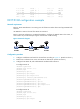
Router A, Router B, Router C and Router D are running OSPF and all of them are in area 0.
Use CR-LDP to create a TE tunnel from Router A to Router D, making sure that the maximum bandwidth
of each link that the tunnel traverses is 10000 kbps and the maximum reservable bandwidth is 5000
kbps.
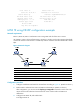
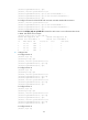
Figure 29 Network diagram
Device Interface IP address Device Interface IP address
Router A Loop0 1.1.1.9/32
Router D
Loop0
4.4.4.9/32
GE 2/1/1 10.1.1.1/24
GE 2/1/1 30.1.1.2/24
Router B Loop0 2.2.2.9/32 Router C Loop0 3.3.3.9/32
GE 2/1/1 10.1.1.2/24
GE 2/1/1 30.1.1.1/24
GE 2/1
/
2 20.1.1.1/24
GE 2/1
/
2 20.1.1.2/24
Configuration procedure
1. Configure IP addresses and masks for the interfaces according to Figure 29. (Details not shown.)
2. Enable OSPF to advertise host routes with LSR IDs as destinations. (Details not shown.)
After configuration, you can execute the display ip routing-table command on each router. The
output shows that all nodes have learned the host routes of other nodes with LSR IDs as
destinations.
3. Configure basic MPLS TE, and enable CSPF:
# Configure Router A.