
R3303-HP HSR6800 Routers MPLS Configuration Guide
117
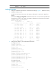
Execute the display ip routing-table command on each router. You can see that all nodes have
learned the host routes of other nodes with LSR IDs as destinations.
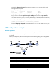
3. Configure basic MPLS TE, and enable RSVP-TE and CSPF:
<RouterA> system-view
[RouterA] mpls lsr-id 1.1.1.9
[RouterA] mpls
[RouterA-mpls] mpls te
[RouterA-mpls] mpls rsvp-te
[RouterA-mpls] mpls te cspf
[RouterA-mpls] quit
[RouterA] interface giabitethernet 2/1/1
[RouterA-GigabitEthernet2/1/1] mpls
[RouterA-GigabitEthernet2/1/1] mpls te
[RouterA-GigabitEthernet2/1/1] mpls rsvp-te
[RouterA-GigabitEthernet2/1/1] quit
[RouterA] interface pos 5/1/1
[RouterA-POS55/1/1] mpls
[RouterA-POS5/1/1] mpls te
[RouterA-POS5/1/1] mpls rsvp-te
[RouterA-POS5/1/1] quit
Follow the same steps to configure Router B, Router C, and Router D.
4. Create an MPLS TE tunnel on Router A:
# Configure the MPLS TE tunnel carried on the primary LSP.
[RouterA] interface tunnel 3
[RouterA-Tunnel3] ip address 9.1.1.1 255.255.255.0
[RouterA-Tunnel3] tunnel-protocol mpls te
[RouterA-Tunnel3] destination 3.3.3.9
[RouterA-Tunnel3] mpls te tunnel-id 10
[RouterA-Tunnel3] mpls te record-route
# Enable hot LSP backup.
[RouterA-Tunnel3] mpls te backup hot-standby
[RouterA-Tunnel3] mpls te commit
[RouterA-Tunnel3] quit
Execute the display interface tunnel command on Router A. You can see that Tunnel 3 is up.
[RouterA] display interface tunnel
Tunnel3 current state: UP
Line protocol current state: UP
Description: Tunnel3 Interface
The Maximum Transmit Unit is 64000
Internet Address is 9.1.1.1/24 Primary
Encapsulation is TUNNEL, service-loopback-group ID not set
Tunnel source unknown, destination 3.3.3.9
Tunnel protocol/transport CR_LSP
Output queue : (Urgent queuing : Size/Length/Discards) 0/100/0
Output queue : (Protocol queuing : Size/Length/Discards) 0/500/0
Output queue : (FIFO queuing : Size/Length/Discards) 0/75/0
Last 300 seconds input: 0 bytes/sec, 0 packets/sec