
R3303-HP HSR6800 Routers MPLS Configuration Guide
118
Last 300 seconds output: 0 bytes/sec, 0 packets/sec
0 packets input, 0 bytes
0 input error
0 packets output, 0 bytes
0 output error
5. Verify the configuration:
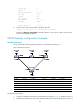
# Execute the display mpls te tunnel command on Router A. You can see that two tunnels are
present with the outgoing interface being GigabitEthernet 2/1/1 and POS 5/1 respectively. This
indicates that a backup CR-LSP was created upon creation of the primary CR-LSP.
[RouterA] display mpls te tunnel
LSP-Id Destination In/Out-If Name
1.1.1.9:6 3.3.3.9 -/GE2/1/1 Tunnel3
1.1.1.9:2054 3.3.3.9 -/POS5/1/1 Tunnel3
# Execute the display mpls te tunnel path command on Router A to identify the paths that the two
tunnels traverse:
[RouterA] display mpls te tunnel path
Tunnel Interface Name : Tunnel3
Lsp ID : 1.1.1.9 :6
Hop Information
Hop 0 10.1.1.1
Hop 1 10.1.1.2
Hop 2 2.2.2.9
Hop 3 20.1.1.1
Hop 4 20.1.1.2
Hop 5 3.3.3.9
Tunnel Interface Name : Tunnel3
Lsp ID : 1.1.1.9 :2054
Hop Information
Hop 0 30.1.1.1
Hop 1 30.1.1.2
Hop 2 4.4.4.9
Hop 3 40.1.1.1
Hop 4 40.1.1.2
Hop 5 3.3.3.9
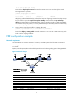
# Execute the tracert command to draw the picture of the path that a packet must travel to reach
the tunnel destination.
[RouterA] tracert –a 1.1.1.9 3.3.3.9
traceroute to 3.3.3.9(3.3.3.9) 30 hops max,40 bytes packet
1 10.1.1.2 25 ms 30.1.1.2 25 ms 10.1.1.2 25 ms
2 40.1.1.2 45 ms 20.1.1.2 29 ms 40.1.1.2 54 ms
The output shows that the current LSP traverses Route B but not Router D.
# Shut down interface GigabitEthernet 2/1/2 on Router B. Execute the tracert command on Router
A to draw the path to the tunnel destination. The output shows that the LSP is re-routed to traverse
Router D:
[RouterA] tracert –a 1.1.1.9 3.3.3.9
traceroute to 3.3.3.9(3.3.3.9) 30 hops max,40 bytes packet
1 30.1.1.2 28 ms 27 ms 23 ms