
R3303-HP HSR6800 Routers MPLS Configuration Guide

152
To set up a VC, the two PEs assign VC labels to each other to set up a pair of unidirectional LSPs
in opposite directions. By VC setup mode, MPLS L2VPN can be implemented in Circuit Cross
Connect (CCC) mode, Static Virtual Circuit (SVC) mode, Martini mode, or Kompella mode. For
more information, see "Implementation of MPLS L2VPN."
3. Set up ACs and bind the ACs to the VC, so the PEs can forward user packets from ACs through the
VC:
a. Set up an AC: Configure the link layer protocol on a PE and the connected CE to set up a link
layer connection (such as a PPP connection) between the PE and the CE.
b. Bind the AC to the VC: For most link layer protocols, you bind the AC to the VC by binding the
PE's Layer 3 interface connected to the CE to the VC. For Ethernet links, you can bind the Layer
3 interface to the VC or bind a service instance to the VC. After the binding, the PE forwards
packets received from the AC to the bound VC, and forwards packets received from the bound
VC to the AC.
Packet forwarding process
MPLS L2VPN implements transparent transmission of Layer 2 user packets over an MPLS or IP backbone
by encapsulating user packets with a VC label and a tunnel tag .
• The tunnel tag is used to transfer packets from one PE to another. If the public tunnel is an LSP tunnel
or an MPLS TE tunnel, the tunnel tag is an MPLS label. If the public tunnel is a GRE tunnel, the tunnel
tag is the GRE header and the transport protocol packet header.
• The VC label identifies a Layer 2 connection to a CE. When receiving a packet from the backbone,
a PE forwards the packet to a CE identified by the VC label.
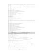
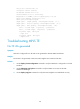
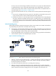
Figure 37 Packet forwarding process
L2 PDU: Layer 2 protocol data unit.
T represents a tunnel tag. V represents a VC label.
As shown in Figure 37, MPLS L2VPN forwards packets in the following steps:
1. After PE 1 receives a Layer 2 packet from CE 1, it adds a VC label to the packet according to the
VC bound to the AC, searches for the public tunnel, adds a tunnel tag to the packet, and then
forwards the packet to the P device.
2. The P device forwards the packet to PE 2 according to the tunnel tag.
3. After PE 2 receives the packet from the public tunnel, it identifies the VC to which the packet
belongs according to the VC label of the packet, deletes the tunnel tag and the VC label from the
packet, and then forwards the resulting packet to CE 2 through the AC bound to the VC.
L2PDU
L2PDU
CE 1
PE 1
CE 2
PE 2
P
L2PDUVT
L2PDUVT