
R3303-HP HSR6800 Routers MPLS Configuration Guide

176
Task Command
Remarks
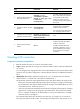
Display MPLS L2VPN AC
information. (In IRF mode.)
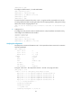
display mpls l2vpn fib ac vpws [ interface
interface-type interface-number
[ service-instance service-instanceid ] ]
[ chassis chassis-number slot slot-number ]
[ | { begin | exclude | include }
regular-expression ]
Available in any view.
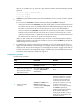
Display MPLS L2VPN PW
information. (In standalone mode.)
display mpls l2vpn fib pw vpws [ interface
interface-type interface-number
[ service-instance service-instanceid ] ] [ slot
slot-number ] [ verbose ] [ | { begin |
exclude | include } regular-expression ]
Available in any view.
Display MPLS L2VPN PW
information. (In IRF mode.)
display mpls l2vpn fib pw vpws [ interface
interface-type interface-number
[ service-instance service-instanceid ] ]
[ chassis chassis-number slot slot-number ]
[ verbose ] [ | { begin | exclude | include }
regular-expression ]
Available in any view.
Display information about one or
all PW classes.
display pw-class [ pw-class-name ] [ |
{ begin | exclude | include }
regular-expression ]
Available in any view.
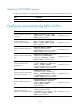
MPLS L2VPN configuration examples
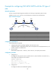
Example for configuring a local CCC connection
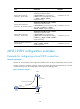
Network requirements
The CEs are connected to the PE through Serial interfaces. The link layer encapsulation protocol is PPP.
Create a local CCC connection on the PE, so the PE can directly forward packets between CE 1 and CE
2 without looking up the forwarding table, improving the forwarding speed.
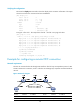
Figure 45 Network diagram
S2/1/0
100.1.1.1/24
S2/1/0
S2/1/0
100.1.1.2/24
S2/1/1
Local CCC connection
CE 1
PE
CE 2
Loop0
172.1.1.1/32