
R3303-HP HSR6800 Routers MPLS Configuration Guide

178
Verifying the configuration:
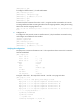
# Execute the display ccc command on the PE to display CCC connection information. The output
shows that a local CCC connection has been established.
[PE] display ccc
Total ccc vc : 1
Local ccc vc : 1, 1 up
Remote ccc vc : 0, 0 up
***Name : ce1-ce2
Type : local
State : up
Intf1 : Serial2/1/0 (up)
Intf2 : Serial2/1/1 (up)
# Ping CE 2 from CE 1. The output shows that CE 1 and CE 2 can ping each other.
[CE1] ping 100.1.1.2
PING 100.1.1.2: 56 data bytes, press CTRL_C to break
Reply from 100.1.1.2: bytes=56 Sequence=1 ttl=255 time=180 ms
Reply from 100.1.1.2: bytes=56 Sequence=2 ttl=255 time=60 ms
Reply from 100.1.1.2: bytes=56 Sequence=3 ttl=255 time=10 ms
Reply from 100.1.1.2: bytes=56 Sequence=4 ttl=255 time=70 ms
Reply from 100.1.1.2: bytes=56 Sequence=5 ttl=255 time=60 ms
--- 100.1.1.2 ping statistics ---
5 packet(s) transmitted
5 packet(s) received
0.00% packet loss
round-trip min/avg/max = 10/76/180 ms
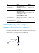
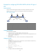
Example for configuring a remote CCC connection
Network requirements
The CEs are connected to the PEs through POS interfaces. The link layer encapsulation protocol is PPP.
Create a remote CCC connection, so CE 1 and CE 2 can exchange Layer 2 packets across the backbone
network.
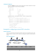
Figure 46 Network diagram
Device Interface IP address Device Interface IP address
CE 1 POS5/1
/
0 100.1.1.1/24
CE 2
POS5/1
/
0 100.1.1.2/24
PE 1 Loop0 10.0.0.1/32
P
Loop0
10.0.0.2/32