
R3303-HP HSR6800 Routers MPLS Configuration Guide

182
Example for configuring SVC MPLS L2VPN with the VC type of
PPP
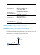
Network requirements
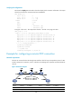
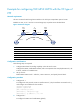
CEs are connected to PEs through POS interfaces. The link layer encapsulation protocol is PPP.
Establish an SVC, so CE 1 and CE 2 can exchange Layer 2 packets across the backbone.
Figure 47 Network diagram
Device Interface IP address
Device
Interface
IP address
CE 1 POS5/1
/
0 100.1.1.1/24
CE 2
POS5/1
/
0 100.1.1.2/24
PE 1 Loop0 192.2.2.2/32 P Loop0 192.4.4.4/32
POS5/1
/
1 10.1.1.1/24
POS5/1
/
0 10.2.2.2/24
PE 2 Loop0 192.3.3.3/32
POS5/1
/
1 10.1.1.2/24
POS5/1/0 10.2.2.1/24
Configuration considerations
The following steps are required:
1. Configure MPLS basic forwarding capability on the PEs and P router:
Configure the LSR ID, enable MPLS and LDP, and run IGP (OSPF in this example) between PE 1, the
P device, and PE 2 to establish LSPs.
2. Set up an SVC:
Enable MPLS L2VPN on PE 1 and PE 2, create a static VC, and specify the VC labels.
Configuration procedure
1. Configure CE 1:
# Configure the link protocol as PPP on interface POS 5/1/0 (the interface connected to PE 1),
and configure an IP address for the interface.
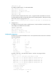
<Sysname> system-view
[Sysname] sysname CE1
[CE1] interface pos 5/1/0
[CE1-POS5/1/0] link-protocol ppp
[CE1-POS5/1/0] ip address 100.1.1.1 24
2. Configure PE 1:
# Configure the LSR ID and enable MPLS globally.
CE 1
CE 2
SVC
PE 1 PE 2P
POS5/1/1
POS5/1/1
POS5/1/0
POS5/1/0
POS5/1/0
POS5/1/1
POS5/1/0
POS5/1/0
Loop0 Loop0 Loop0